Serial NO. : H01917007-EN
Date of Editing : 2021-07-20
Questions : One-way multi door interlocking solution AR-401-IO-1709R
Problem Solving :
- Required/Applied Condition:
--Input devices: push button, door sensor
--Output devices: door lock, alarm
--AR-401-IO-1709R with special firmware of:
4 doors interlocking à 401RO8DI16_V0207_210621 DOOR_INTERLOCK_4.ISP
8 doors interlocking à 401RO8DI16_V0207_210621 DOOR_INTERLOCK_8.ISP
- Function:
Interlocking is a set of doors controlled by a programmed controller to deny second door access when first door remained opened. Suitable for prison or clean room with multi-group access over a space that shares interlocking solution
- Problem Solving:
One way interlocking solution for four doors or eight doors control, including fire alarm/emergency button to release all doors event when triggered.
This FAQ will covers:
1. 4 doors interlocking
1.1 Programming Logic
1.2 I/O Assignment
2. 8 doors interlocking
2.1 Programming Logic
2.2 I/O Assignment
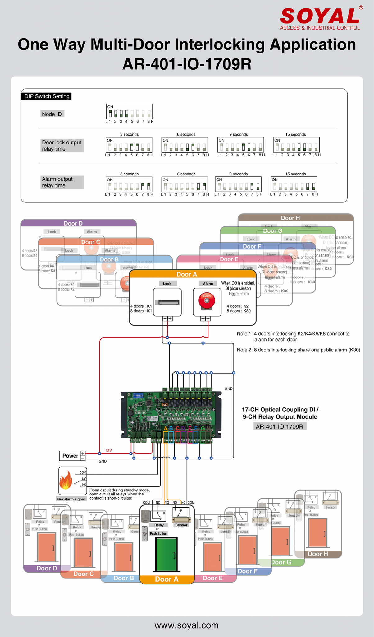
3. DIP Switch setting
4. Wiring Diagram (access by push button / access controller)
A. 4 doors interlocking
A-1 Programming Logic
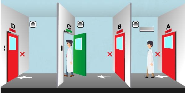
Door 1 open -> Door 2/3/4 cannot be opened
Door 2 open -> Door 1/3/4 cannot be opened
Door 3 open -> Door 1/2/4 cannot be opened
Door 4 open -> Door 1/2/3 cannot be opened
- Normal access: press push button to enter door
- If door 1/2/3/4 force open without normal access, will trigger alarm
- If one of the four doors is open, the second door could not be opened. Example: Door 1 is opened, normal access on door 2 will result in door 2 still remain as locked.
- All doors will be auto released when fire alarm event is triggered
A-2 I/O Assignment
| Door | Egress | Door Sensor | Door Lock | Alarm |
| Door 1 | DI1 | DI2 | DO1 | DO2 |
| Door 2 | DI3 | DI4 | DO3 | DO4 |
| Door 3 | DI5 | DI6 | DO5 | DO6 |
| Door 4 | DI7 | DI8 | DO7 | DO8 |
| Fire Alarm | FIRE (CN5) | |||||||||||||||||||||||||||||||||||||||||||||||||||||||||||||||||||||||||||||||||||||||||||||||||||||||||||||||||||||||||||||||||||||||||||||||||||||||||||||||||||||||||||||||||||||||||||||||||||||||
B. 8 doors interlocking
B-1 Programming Logic
The same logic with 4 doors, the only different, there is no individual alarm output for each door.
Door 1 open -> Door 2/3/4/5/6/7/8 cannot be opened
Door 2 open -> Door 1/3/4/5/6/7/8 cannot be opened
Door 3 open -> Door 1/2/4/5/6/7/8 cannot be opened
Door 4 open -> Door 1/2/3/5/6/7/8 cannot be opened
Door 5 open -> Door 1/2/3/4/6/7/8 cannot be opened
Door 6 open -> Door 1/2/3/4/5/7/8 cannot be opened
Door 7 open -> Door 1/2/3/4/5/6/8 cannot be opened
Door 8 open -> Door 1/2/3/4/5/6/7cannot be opened
- Normal access: press push button to enter door
- If door 1/2/3/4/5/6/7/8 open without normal access, will trigger alarm (public alarm)
- If one of the doors is open, the second door could not be opened. Example: Door 1 is opened, normal access on door 2 will result in door 2 still remain as locked.
- All doors will be auto released when fire alarm event is triggered
B-2 I/O Assignment
| Door | Egress | Door Sensor | Door Lock | Alarm |
| Door 1 | DI1 | DI2 | DO1 | DO9 (public alarm) |
| Door 2 | DI3 | DI4 | DO2 | |
| Door 3 | DI5 | DI6 | DO3 | |
| Door 4 | DI7 | DI8 | DO4 | |
| Door 5 | DI9 | DI10 | DO5 | |
| Door 6 | DI11 | DI12 | DO6 | |
| Door 7 | DI13 | DI14 | DO7 | |
| Door 8 | DI15 | DI16 | DO8 |
| Fire Alarm | FIRE (CN5) | |||||||||||||||||||||||||||||||||||||||||||||||||||||||||||||||||||||||||||||||||||||||||||||||||||||||||||||||||||||||||||||||||||||||||||||||||||||||||||||||||||||||||||||||||||||||||||||||||||||||
3. DIP Switch setting
| DIP | 1 | 2 | 3 | 4 | 5 | 6 | 7 | 8 |
| Function | Node ID | Door relay time | Alarm relay time | |||||
| Value | Range 1~16 (maximum 16 units) | 3/6/9/15sec | ||||||
4. Wiring Diagram
Wiring diagram for one way 4 doors or 8 doors interlocking solutions with access by push button or access controller (two options)