This function offer different delay timer between input and output when selecting AR-403 module as ‘Delay’ Function.
| DI trigger | DO | Function |
| DI 0 ► | DO 0 | Interval Operation, Falling Edge Mode |
| DO 1 | Trigger-at-Release Timer, Rising Edge Mode | |
| DO 2 | Toggle Mode | |
| DO 3 | Undistorted Output Delay |
T= Input Trigger
Td= Input delay time (pulse)
Q= Output Trigger
Qd= Output delay time (set value on Commview tools)
Qi= Output time (set value on Commview tools)
Tp= interval delay between input T0 and T1
Output Mode 1: DI 0→DO 0- Interval Operation, Falling Edge Mode
DI 0 trigger DO 0 under condition:
Condition 1:
- The output turn ON at the same time as the input turned ON
- Output OFF after a set of time (Qi)
- Input trigger (T) in Output 1 mode does not have delay time
Condition 2:
- When continuous input (T) is triggered before output time (Qi) is time out, the output time (Qi) will be accumulated at the same time last trigger input (T1) is ON.
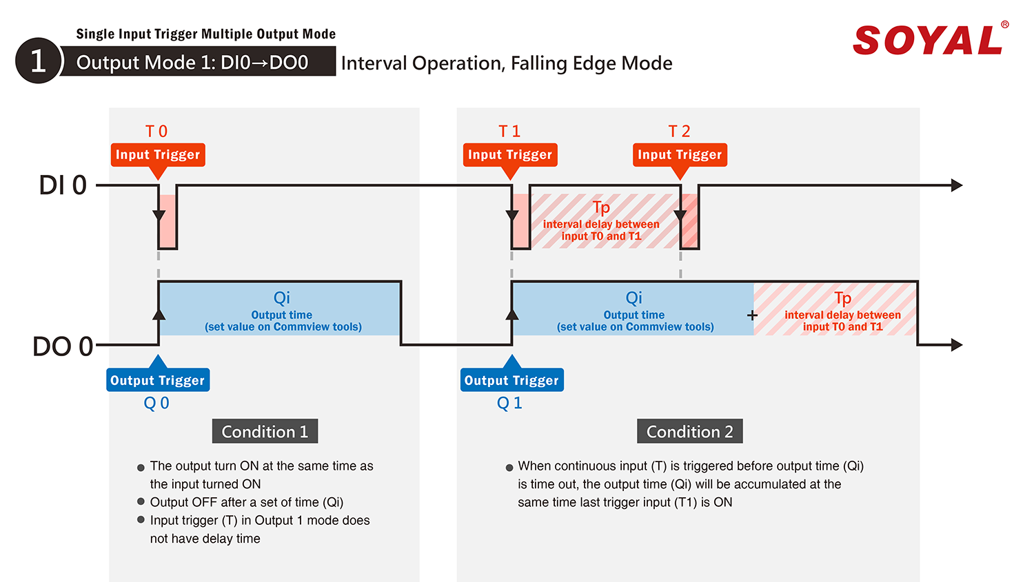
Example:
Qi set as 5 seconds
When input is ON (T0), output will be ON (Qi) for 5 seconds before time out (OFF). During the process if within two seconds (Tp), another input is triggered (T1), so the output will be OFF after 7 seconds.
Output Mode 2: DI 0→DO 1- Trigger-at-Release Timer, Rising Edge Mode
DI 0 trigger DO 1 under condition:
Condition 1:
- The output turns ON after input (T) triggered
- Output OFF after a set of output time (Qi)
Condition 2:
- When continuous trigger output (Q) is triggered before output time (Qi) is OFF, the total output time will be accumulated after the last trigger input (T1) is release, with condition output time value (Qi) is less than interval delay Tp + last trigger input T1 combined.
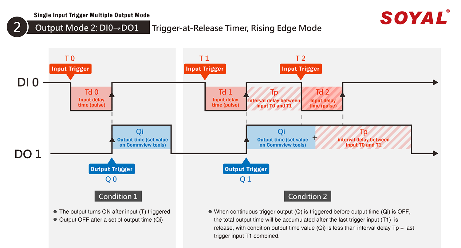
Example:
Qi set as 5 seconds, Td0 = 1 sec, Td1 = 3 sec, Tp = 1 sec
Total output time will be ON for total 8 seconds
Output Mode 3: DI 0→DO 2- Toggle Mode
DI 0 trigger DO 2 under condition:
Condition 1:
- The output ON/OFF is determine by DI1 (T) status until DI1 (T) switch to another mode (ON become OFF, OFF become ON)
- T is input trigger, Q is output trigger
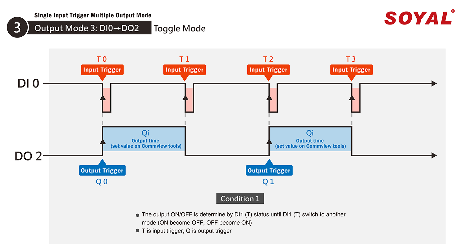
Example:
Input T0 will directly trigger output Q0. Until the next input is triggered (T1), output will remain as Q0. When T1 is triggered, at the same time output will be changed from Q0 to Q1.
Output Mode 4: DI 0→DO 3- Undistorted Output Delay
DI 0 trigger DO 3 under condition:
Condition 1:
- When delay output time (Qd) less than output delay time (Qi), output time is predetermined by input delay time (Qi=Td)
Condition 2:
- When input delay time is (Td) is greater than the output delay time (Qd), total output time (Qi) is equivalent to input delay time (Td).
* This is under the condition output will still triggering after output delay time is time out.
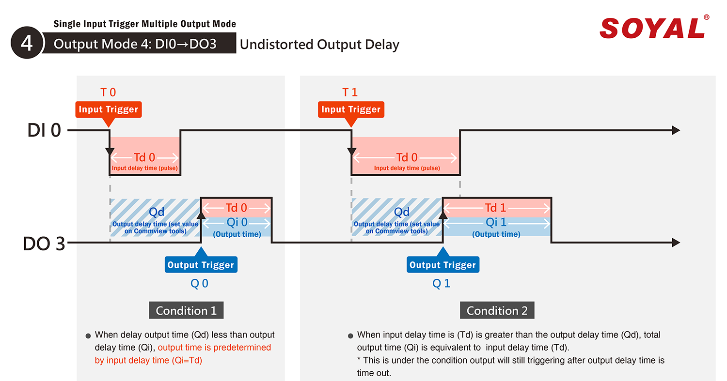
Example 1:
Input delay time (Td) set as 2 seconds, output delay time (Qd) set as 5 seconds, automatically output time (Qi) is 2 seconds
Example 2:
Input delay time (Td) set as 6 sec, output delay time (Qd) set as 5 sec.
After 5 seconds, although input is still triggering, total output will be 11 seconds.