Description:
This case demonstrates the application of cycle-based output using DI0 to trigger DO0. Additionally, a TIMER is utilized to control the output duration, shutting off the output after N seconds. This setup can be practically applied in parking lot lanes, where vehicle entry into the lane triggers an infrared sensor, activating a buzzer or relevant lights to indicate vehicle movement and ensure lane safety.
.png)
WEB Configuration Interface & Ladder Diagram: :
Ladder Diagram (Providing two configuration methods)
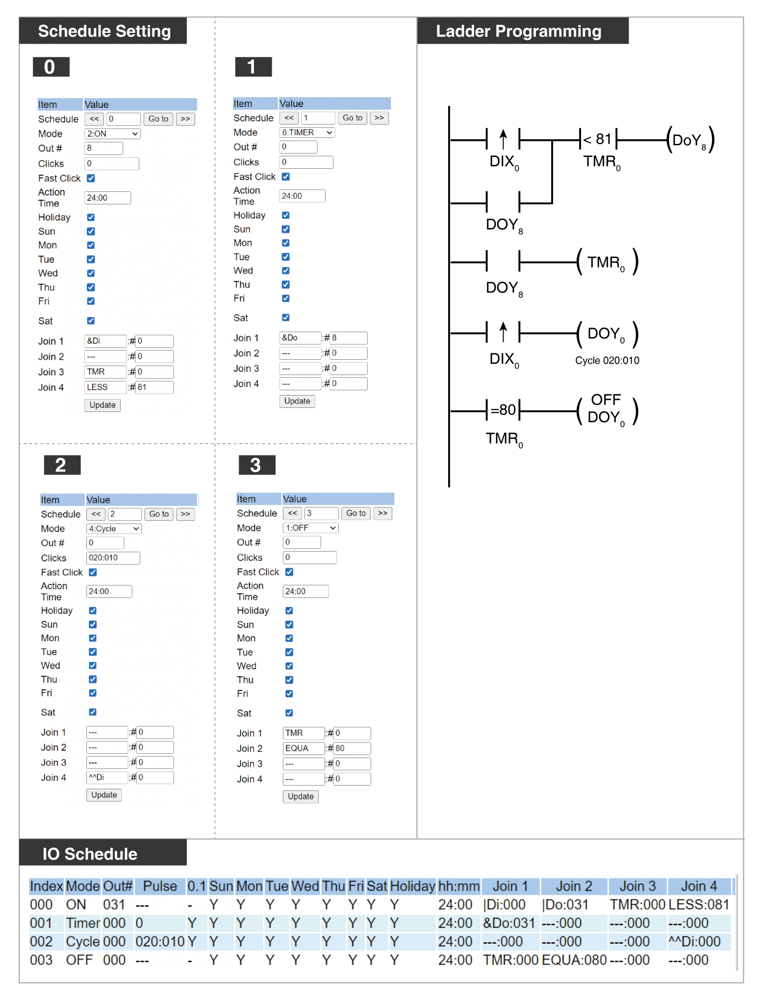
(1) Using Timer for Timing and Disabling Cycle Output
Index 000: Set the trigger condition for virtual output M8 (Self-hold & TMR:000 < 81)
Index 001: Set the trigger condition for TMR:000 (M8 ON)
Index 002: Set the trigger condition for Y0 (X0 edge trigger)
Index 003: Set the close condition for Y0 (TMR:000 = 80)
- X0/X1/.../Xn represent physical input points DIX0/DIX1/.../DIXn
- Y0/Y1/.../Yn represent physical output points DOY0/DOY1/.../DOYn
- M0/M1/.../Mn represent virtual output points DOM0/DOM1/.../DOMn
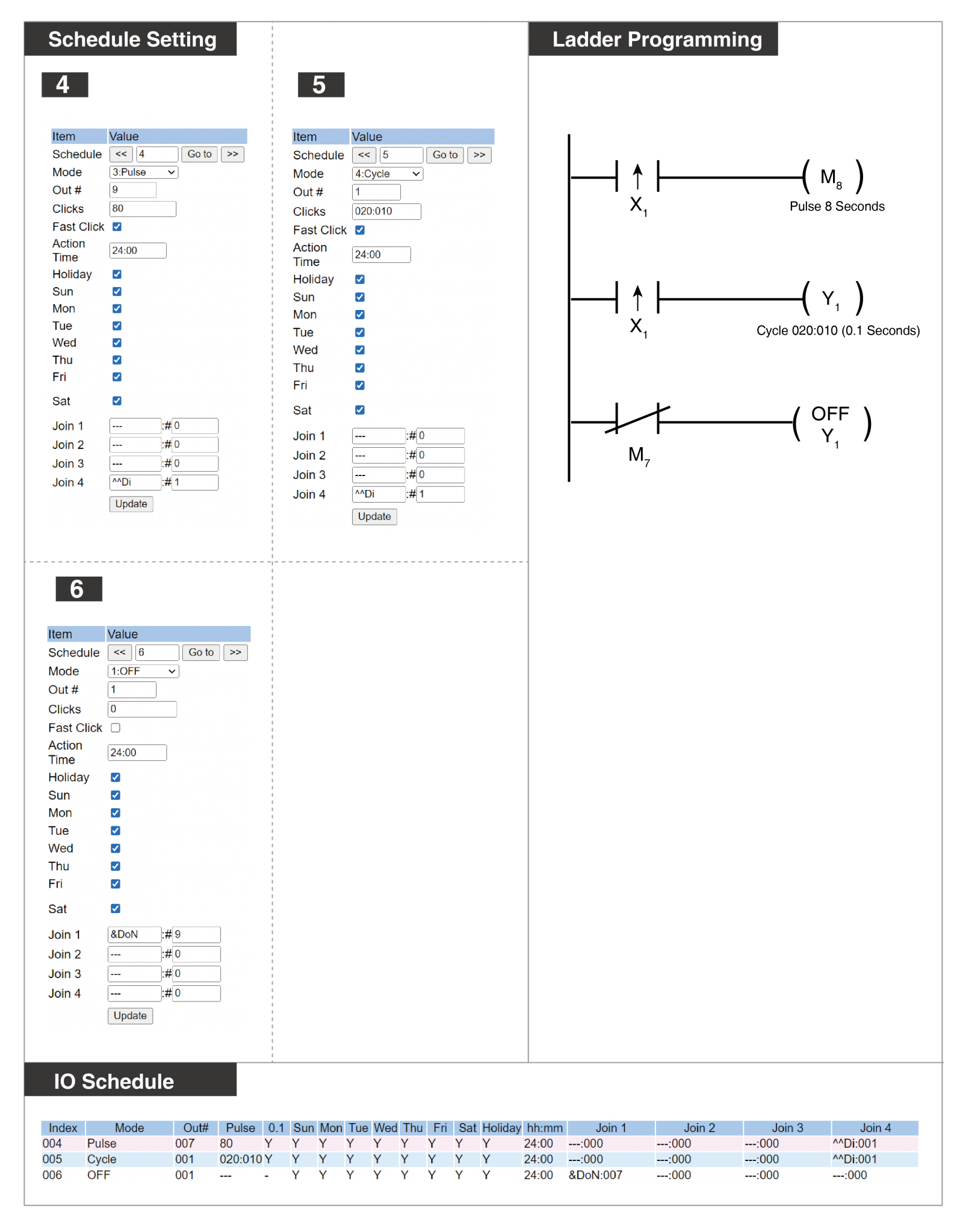
(2) Using Pulse for Timing and Disabling Cycle Output
Index 004: Set the trigger condition for virtual point M7 (X1 edge trigger), executing an 8-second output after trigger
Index 005: Set the trigger condition for physical point Y1 (X1 edge trigger), initiating cycle output after trigger
Index 006: Set the OFF condition for Y1 (M7 OFF)
- X0/X1/.../Xn represent physical input points DIX0/DIX1/.../DIXn
- Y0/Y1/.../Yn represent physical output points DOY0/DOY1/.../DOYn
- M0/M1/.../Mn represent virtual output points DOM0/DOM1/.../DOMn