SOYAL TECHNOLOGY CO., LTD

Membership Center
0
Browsing Records
Programmable Logic Controller (PLC) with Web Interface
2023-08-23
4753

Hardware Features:

  • MOBUS-TCP to RTU Gateway X 1,which can be used for RTU devices/meters and analog interfaces.
  • Comes with one RS-485 I/O expansion communication module, allowing for the expansion of I/O points up to 256 points.
  • The PLC itself has 8 built-in relay outputs and 8 opto-coupler inputs. It can be expanded to a maximum of 256 digital inputs (DI) and 256 digital outputs (DO).


Logic Programming Features:

  • Programmable logic controller with calendar time, holiday conditions, counters, timers, DI, and DO functions.
  • Support for calendar time and holiday condition settings.
  • Logic expressions: Supports a web-based editing interface for 64 logic expressions.
  • Logic conditions: Every hour / Every day / Every week / Calendar holiday / Timer / Counter / AND / OR / Edge event.
  • Output types: ON/OFF / One Shot / Continue Pulse / Counter / Timer
  • The actual digital output points (DO) are shared with logical virtual points, meaning that unused output points within the addressing range can be utilized as virtual points.
  • Timers: It features 8 timers, with the option to select a timing unit of 0.1 seconds or 1.0 second. The maximum value for a single timer is 255. These timers can be connected in series with other counters, enabling a maximum timer duration of up to 3000 years.
  • Counters: It possesses 8 edge-triggered counters, with a maximum value of 255 for each individual count. These counters can be linked together with other counters for usage, allowing for a maximum count that can exceed 100 million times.


Programming User Interface:

Built-in easy to program and interactive user interface

  • [ IO Expend Nodes ] 

  • [ IO Schedule ] 

  • [Schedule Setting ] 

  • [Clock ] 

  • [Holiday ] 


Actual Case Studies : 

A. Basic Application Ccenarios

Conditions:
When X0 to X7 are triggered, execute ON for Y0 to Y7.
When X0 to X7 are shorted, execute OFF for Y0 to Y7.

Instruction Explanation:

  • Index 000: When X0 is triggered, execute ON for Y0.
  • Index 001: When X1 is triggered, execute ON for Y1.
  • ‧‧‧‧‧‧‧‧‧
  • Index 007: When X7 is triggered, execute ON for Y7.

Referenced Commands:  Level-triggered operation.


Conditions:
When X0 to X3 have a rising edge trigger, execute ON for Y0 to Y3; when X0 to X3 are shorted, the output does not reset.
When X4 has a rising edge trigger, execute OFF for Y0 to Y3

Instruction Explanation:

  • Index 000: When X0 has a rising edge trigger, execute ON for Y0
  • ‧‧‧‧‧‧‧‧‧
  • Index 003: When X3 is triggered, execute ON for Y3
  • Index 004: When X4 is triggered, execute OFF for Y0
  • ‧‧‧‧‧‧‧‧‧
  • Index 007: When X4 is triggered, execute OFF for Y3

Edge application: Level-triggered operation.


  • Holiday trigger only

When only the Holiday option is selected in the Week/Holiday condition, it means this schedule will trigger only on holidays.
Example: Whenever there is a holiday, the traffic signal will start flashing at midnight 00:01 and end at 23:59 of the same day.

  • Weekdays trigger only

In the Week/Holiday condition, selecting only Monday to Sunday without selecting holidays means that this schedule will trigger only on weekdays.
Example: On weekdays (non-holidays), turn on the lobby lights at 8:00 in the morning and turn them off at 5:00 in the afternoon.

  • Holiday & Specific Weekdays trigger

In the Week/Holiday condition, selecting both Monday to Sunday and holidays means that this schedule will trigger on specified weekdays or holidays.
Example: Whenever it's Wednesday or a holiday, turn on the driveway lights at 6:00 in the evening and turn them off at 10:00 at night.


Conditions:
1. At the entrance of the driveway, when the infrared sensor X0 is triggered, it activates the opposite exit signal light Y0.
2. The signal light operates in a cycle of ON for 0.3 seconds > OFF for 0.3 seconds >   ON for 0.3 seconds > OFF for 0.3 seconds, and so on.
3. At the end of the driveway entrance, there's another set of infrared sensors (X1). The signal light Y0 stops outputting only after a vehicle triggers X1 and leaves.
4. The above operation sequence is triggered only on holidays, defined here as Fridays, Saturdays, and Sundays (excluding public holidays).
5. For holiday settings. You can manually select holidays in the [Holiday] section or edit and download them in 701ClientSQL.


Instruction Explanation:

  • Index 000: Output Y0 operates in a cycle mode, with a time unit of ON for 0.3 seconds and OFF for 0.3 seconds, repeating. It triggers only on holidays (requires setting Holiday to select all Thursdays, Fridays, and Saturdays throughout the year), with the trigger condition being the rising edge of X0.
  • Index 001: Turns off Y0, triggered by holidays or the falling edge of X1.

Referenced Commands:
Cycle / Holiday condition / Rising edge trigger / Falling edge trigger On Fridays, Saturdays, or Sundays, activate the driveway lights at 6:00 in the evening until 10:00 at night


Conditions:
The counter is equipped with a door-open button, directly controlled through WEB PLC, sensing one press to open and another to close.

Instruction Explanation:

  • Index 000: Y0 operates in Toggle mode, triggered by the rising edge of X0

Referenced Commands:
Toggle / Edge trigger


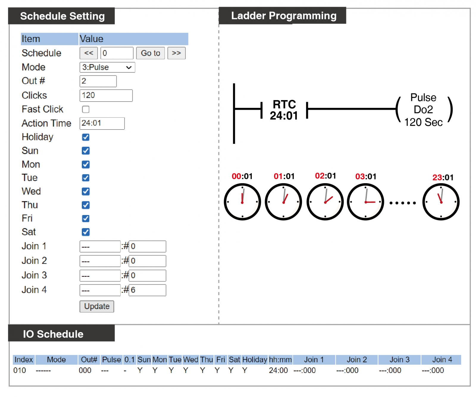
Conditions:
At the 01 minute of each hour, Motor (Y2) will start for 120 seconds and automatically stop when the time is up.

Instruction Explanation:
This configuration uses Pulse output for 120 seconds, triggered only by the time condition. 
The Action Time is set for 24:01 to 24:59, which will trigger every hour. For detailed differences, refer to  Action Time.

Referenced Commands:
Pulse output / Action Time


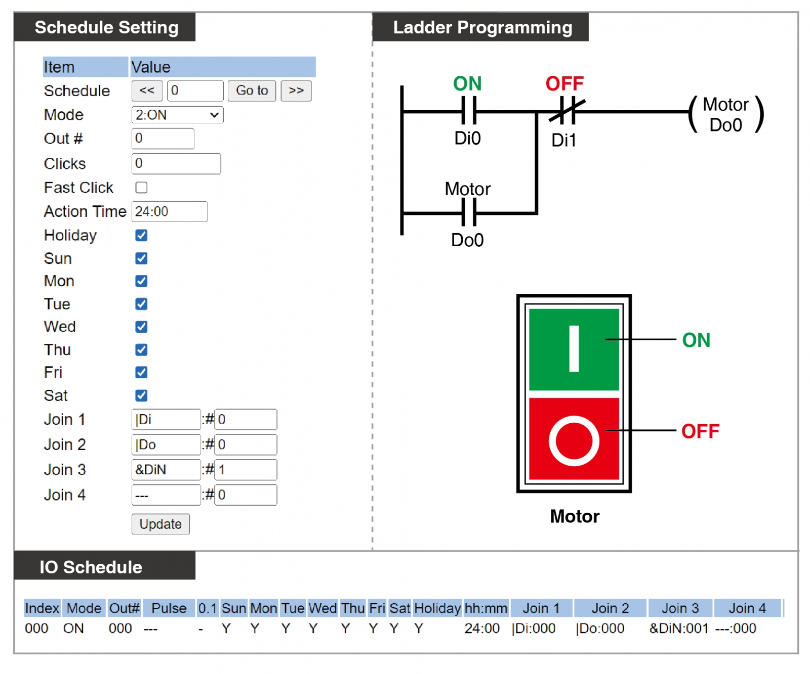
The above are the methods for configuring self-holding on AR-401-IO-0808R, which can be done using the traditional PLC approach. 

Instruction Explanation :

The AR-401-PLC-0808R supports traditional self-holding control settings. When X0 or Y0 is in conducting state, and meantime X1 is in short circuit state, then Y0 will be turned ON.


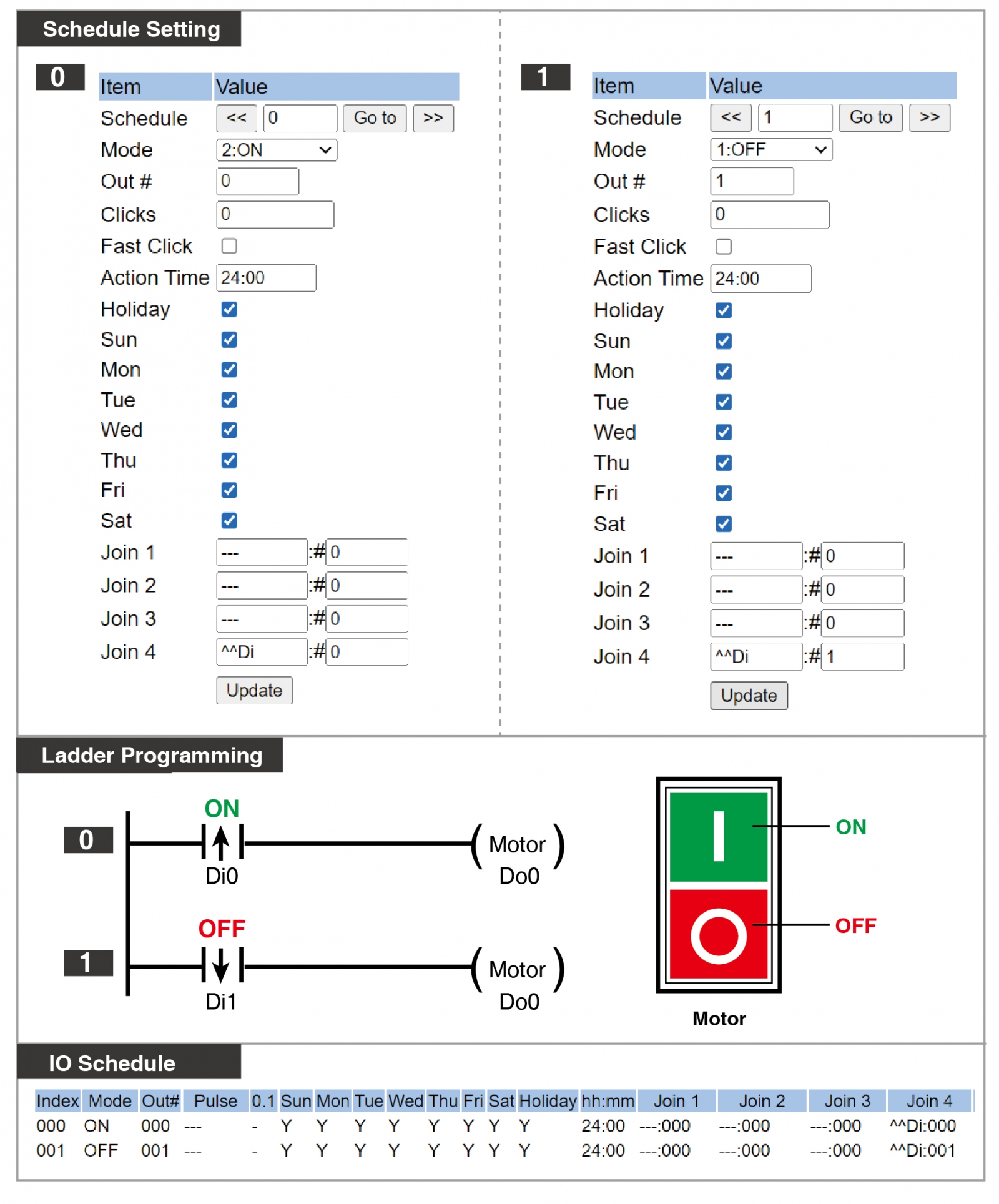
AR-401-10-0808R supports Edge Trigger Mode, allowing for the simple design of self-holding control with the same action mode as described in section 6-1 Motor Self-holding Control.

Instruction Explanation :
ON Y0 when X0 triggered with rising edge; OFF Y0 when X1 triggered with rising edge.

Referenced Commands:
Edge Trigger (rising) / ON / OFF

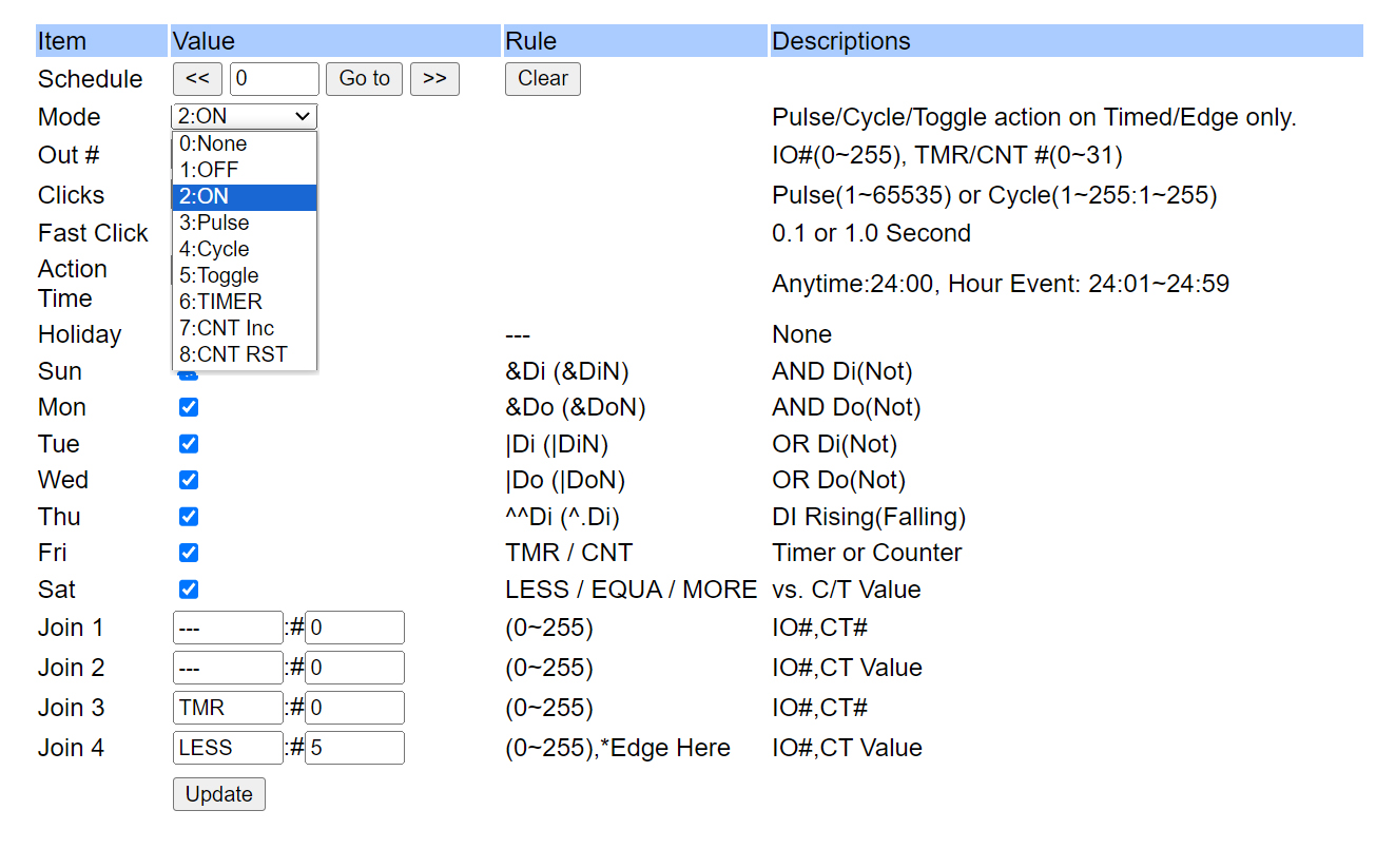
 ※Edge trigger conditions must be set in Join4.

B. Intermediate application scenarios

Conditions:
There is a dual infrared sensing alarm system on-site (Infrared A / Infrared B). When Infrared A is triggered, a timer of 30 seconds starts. If Infrared B is also triggered within 30 seconds, the alarm Y0 will be activated. After the alarm occurs, it needs to be deactivated by pressing the reset button by the management personnel.

Instruction Explanation:

  • Index 000: Infrared A (X0) triggers M8 on the rising edge.
    Index 001: M8 triggers TIMER000.
    Index 002: When TIMER000 reaches 30, M8 turns off.
    Index 003: While M8 is ON, Infrared B (X1) triggers the alarm Y0 on the edge.
    Index 004: Management room reset button triggers the closing of alarm Y0 output 
                       on the rising edge.

Referenced Commands:  Edge trigger / Timer counter


Conditions: 
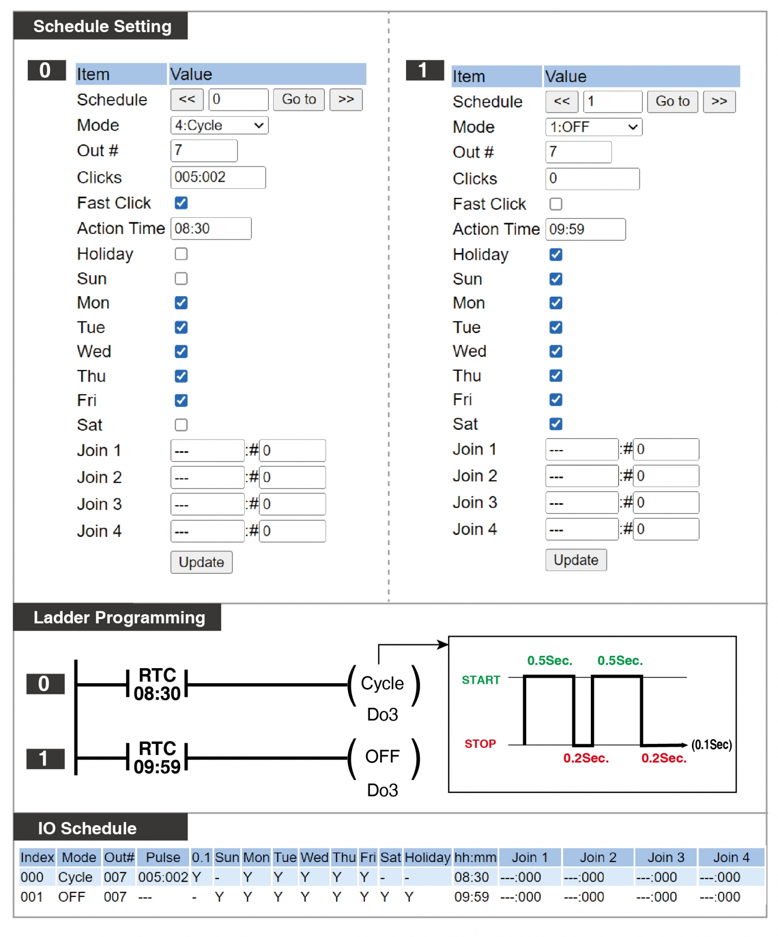
1. Lights flash on weekdays, Monday to Friday, in the morning for 90 minutes, with no
 action on Saturdays, Sundays, or holidays.
2. The flashing pattern of the lights is ON for 0.5 seconds > OFF for 0.2 seconds > ON for 0.5 seconds > OFF for 0.2 seconds, and so on.
3. This example uses a fixed time point (8:30 AM) as the trigger condition.

Instruction Explanation: 
Set the activation condition for the cycle to be from Monday to Friday at 08:30, and the deactivation condition to be any day of the week and the time to be 09:59.

Referenced Commands:
Holiday Setting / Time Trigger Condition / Fast Click Time Unit Switching (1 second / 0.1 seconds) / Cycle Output

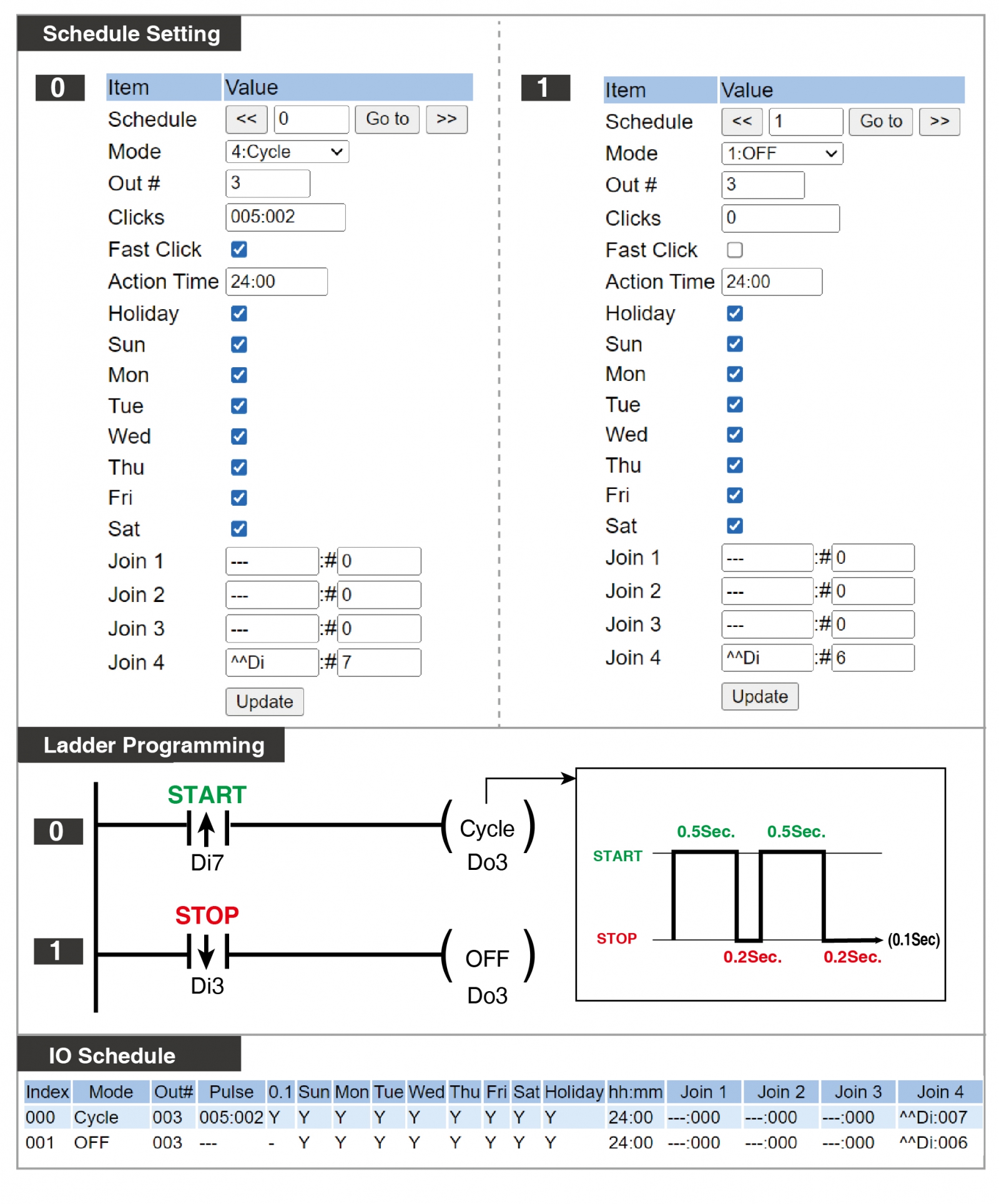
Conditions:
Pressing the button A edge trigger (X7) starts executing the Cycle output, and pressing the button B edge trigger (X6) stops the output.
※Edge trigger conditions must be set in Join4.

Instruction Explanation: 
The operation is set as a cycle output with a unit of 0.1 seconds, cycling through 0.5/0.2/0.5/0.2 seconds... pattern.

Referenced Commands:
Fast Click Time Unit Switching (1 second / 0.1 seconds) / Cycle Output / Edge Trigger (rising)

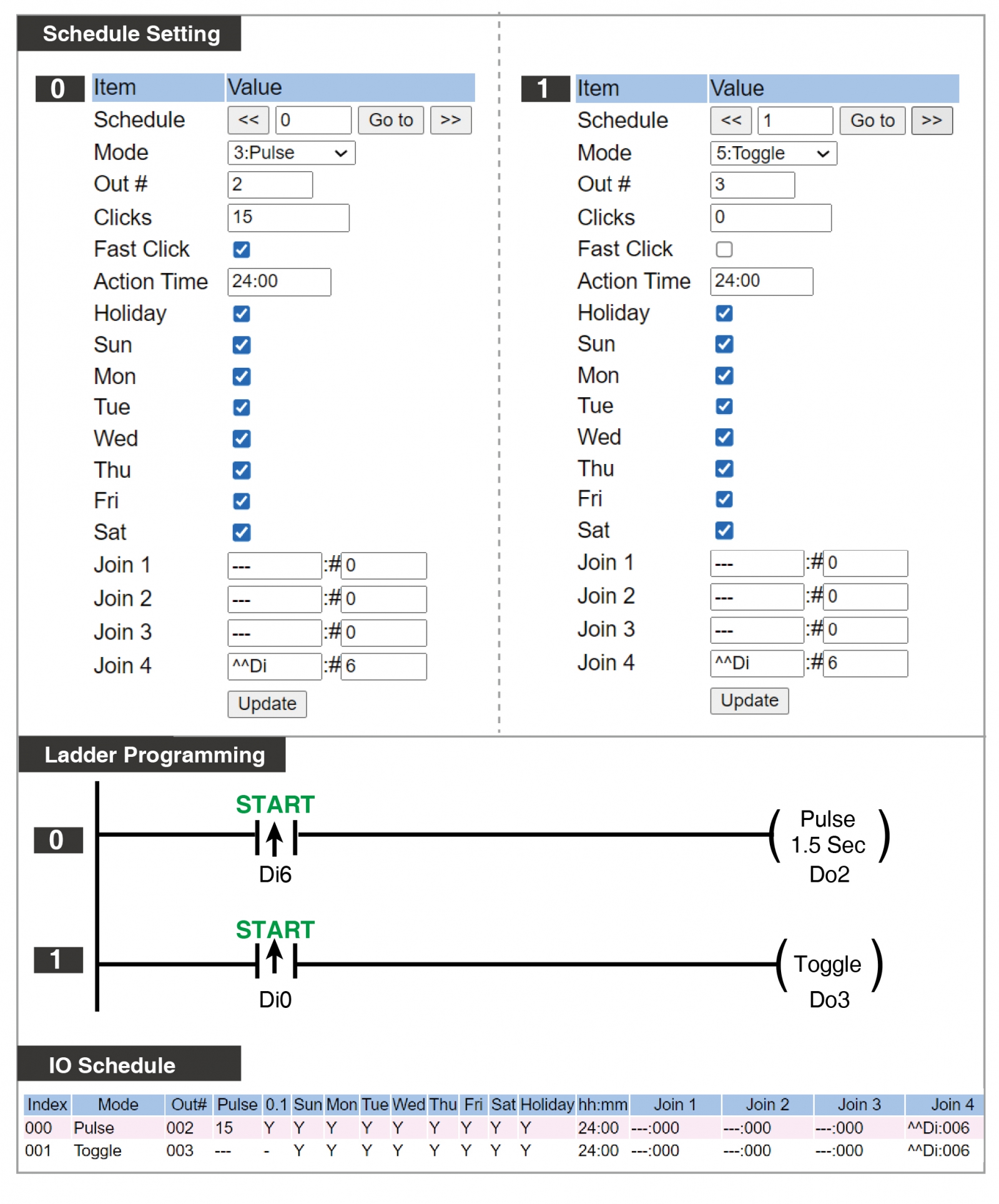
Conditions:
Press the button (X6) to trigger two outputs:
(1) Bulb A lights up for 1.5 seconds.
(2) Bulb B changes the cycle between on and off, triggering ON once and then triggering OFF.

Instruction Explanation:
Pressing X6 triggers Y2 to activate for 1.5 seconds. Pressing the button (X6) changes the 
light's state (on/off) in a cyclic manner. (※Edge trigger conditions must be set in Join4.)

Referenced Commands:
Pulse Output / Toggle
 

Conditions:
On-site, there is a light signal device that needs the PLC to provide an output for 10 seconds every minute.

Instruction Explanation:

  • Index 000: Timer000 < 60, meaning TMR 000 will continuously cycle between 0 and 60 seconds.
  • Index 001: Pulse output for 10 seconds, condition is TMR 000 = 0.

※Since TMR 000 continuously cycles between 0 and 60 seconds, each time TMR000 = 0, it will execute a Pulse output. This setup meets the requirement of providing a 10-second output every minute.
This configuration is suitable for short cycle outputs, directly specifying on-site cycles of every n seconds/minutes; for outputs required every hour or longer, refer to A-3 for hourly timed triggers.

Condition:
There is a traffic signal on-site, and after triggering, the green light stays on for 20 seconds. After the green light, the yellow light stays on for 5 seconds, and after the yellow light, the red light stays on for 20 seconds.

Instruction Explanation:
This example uses the Pulse function to control time, and conditions like the previous output OFF combined with the next output ON to trigger the next actual output. This example can be extended continuously until all 64 schedules are used up.

  • Index 000: The actual output for the green light, triggers Y0 for 20 seconds with the rising edge of X0, indicating the green light for 20 seconds.
  • Index 001: The virtual output for the yellow light, triggers M8 for 25 seconds with the rising edge of X0, using M8-Y0 (25-20=5) for the 5 seconds of the yellow light output.
  • Index 002: The virtual output for the red light, triggers M9 for 45 seconds with the rising edge of X0, using M9-M8 (45-25=20) for the 20 seconds of the red light output.
  • Index 003: The actual output for the yellow light, lights up the yellow light for a total of 5 seconds when Y0 is OFF and M8 is ON.
  • Index 004: The actual output for the red light, lights up the red light for a total of 20 seconds when M8 is OFF and M9 is ON.

Referenced Commands:
Pulse Output / Virtual Point / ON / Rising Edge Trigger


Conditions:
Card readers are installed in each building of the community and are used as security patrol points. These card readers need to be swiped by security personnel within ten minutes at four time points each day: 00:00, 06:00, 12:00, and 18:00. Otherwise, it will trigger an alarm to notify the management center.

Instruction Explanation:

  • Index 000: Regardless of weekdays or holidays, at 00:00 every day, execute ON M8
  • Index 001: Once M8 is activated, TIMER 000 starts counting.
  • Index 002: When TIMER 000 exceeds 600 seconds, execute ON Y0
  • Index 003: After the patrol personnel swipe the card, the card reader relay triggers X0,  executing OFF M8

Referenced Commands:
Scheduled trigger / TIMER / Edge trigger

※ The following example is for a single time alarm (00:00). Please set and test other time points accordingly.

Conditions:
An anti-false trigger button be installed on-site, and the button can trigger two different actions:
1. If button X0 is pressed and not pressed again within ten seconds, a one-second output will be triggered to the central alarm system.
2. If button X0 is pressed and pressed again within ten seconds, no signal will be sent.

Instruction Explanation:

  • Index 000: When X0 is triggered(Rising-edge Triggering), virtual point M10 ON.
  • Index 001: When M10 is ON, TMR 000 starts.
  • Index 002: When TMR 000 equals ten seconds, it outputs Y0, Pulse Output for one second.
  • Index 003: When TMR 000 equals ten seconds, M10 turns OFF, resetting the virtual point M10 to initial state.

Referenced Commands:
Toggle / Edge Trigger / TIMER / Pulse / OFF


C. Advanced Application Scenarios

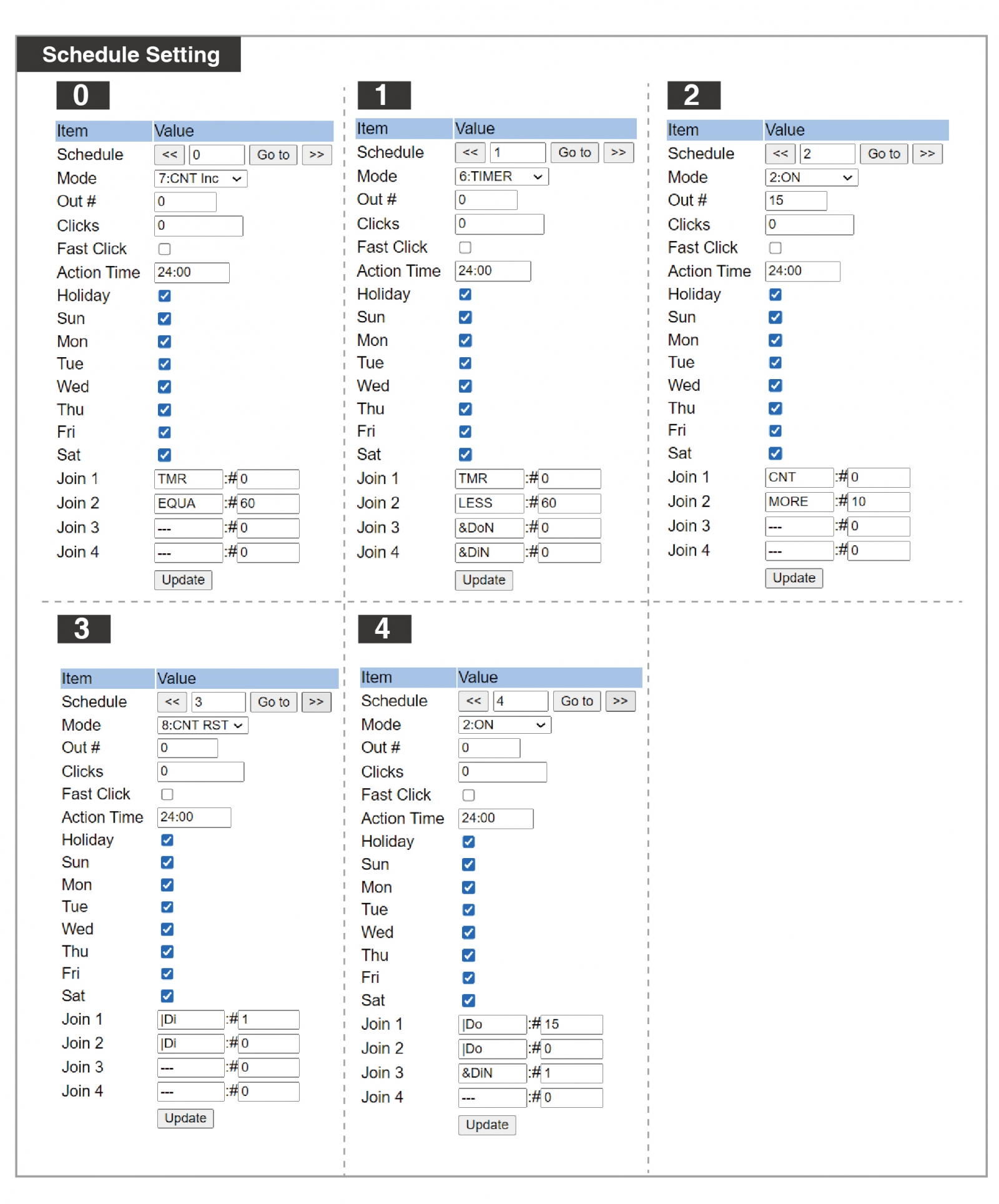
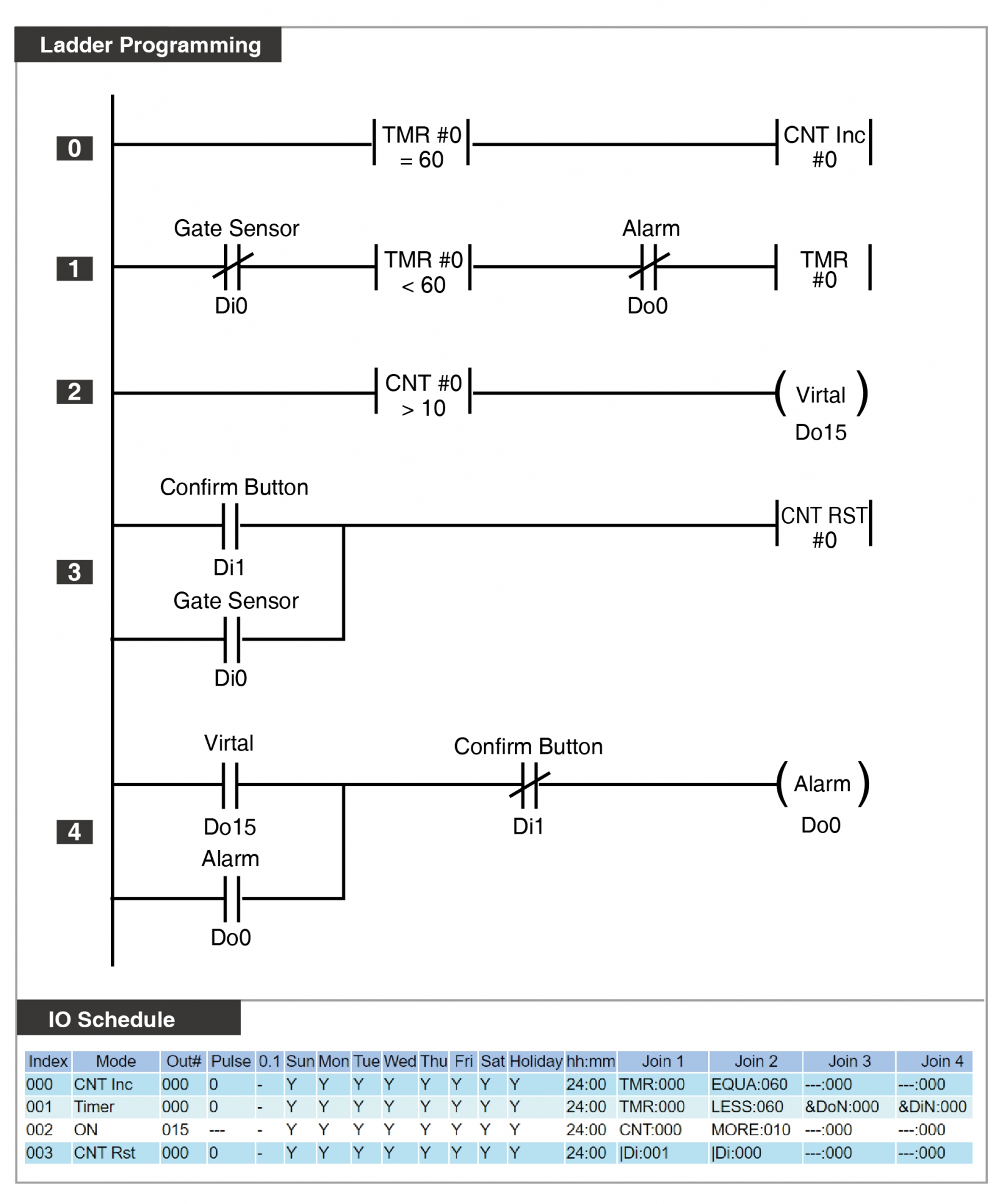
Trigger the Alarm When Door Open more than 10 minutes 

Condition:
The main door is equipped with door sensor, serving as the condition for starting the Timer. When the main door is open (door sensor short-circuited) for more than 10 minutes, it will trigger an alarm. The alarm will persist until the main door is closed or until the administrator presses the release button.

Instruction Explanation:

  • Index 000: When the Timer000 is equal to 60, Counter Counter000 will increment by 1.
  • Index 001: When Timer000 is less than 60, it will cyclically count from 0 to 60 seconds. Additionally, there are required conditions: Y0 OFF (alarm not triggered yet)  and X0 OFF (door open, door sensor short-circuited).
  • Index 002: When the Counter000 exceeds 10, it will trigger the virtual output M15  (used as the trigger condition for Y0 alarm output).
  • Index 003: The trigger conditions for resetting the Counter000 are X0 (door closed) or X1(pressing the release button).
  • Index 004: Y0 alarm is self-holding function, with the condition of virtual output M15 ON (door open for ten minutes) and X1 OFF (alarm release button short-circuited).

Referenced Commands:
Timer / Counter / Virtual Output / Self-holding


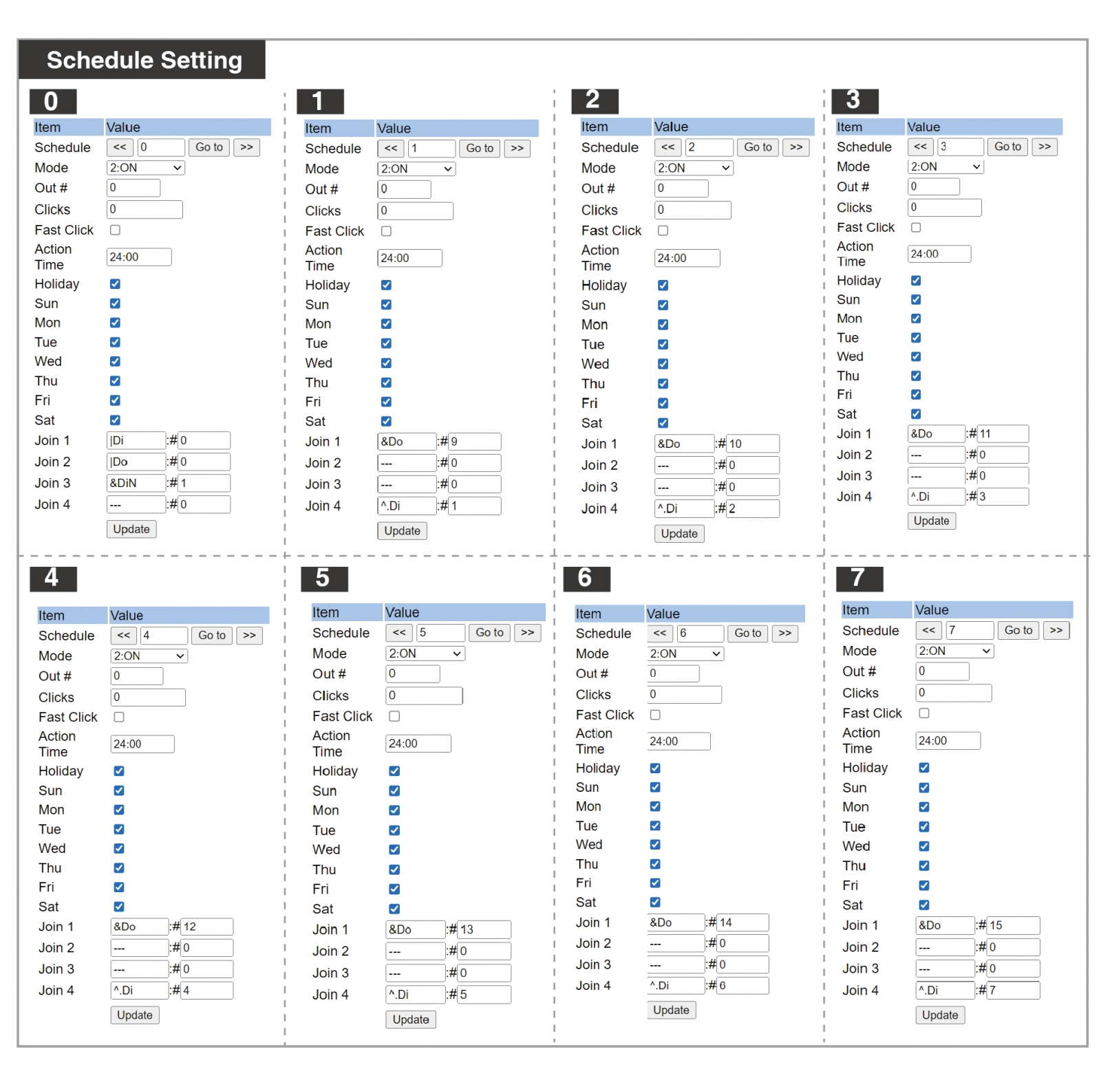
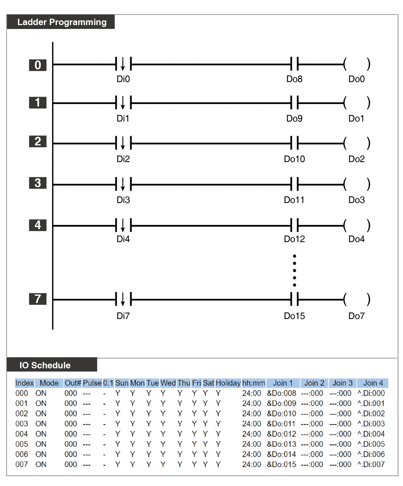
For this example, we have eight infrared devices with edge-triggered Inputs 0-7, and we want to activate corresponding Outputs 0-7 for alarm indicators. Additionally, the manager requires the on-site personnel to have manual control over whether the corresponding alarm indicators should be activated after each infrared device trigger.

Answer: Set the output mode of 0-7 point to ON. When the condition is met for triggering, activate the output alarm indicator. The condition content is edge-triggered (^.Di), and the virtual point Y8 (&Do) must be in “on” state simultaneously to trigger the corresponding alarm indicator.
The virtual output M8-15 can be triggered through 701Client graphical control or developed using third-party software with Modbus triggering.
 

Application Architecture : 


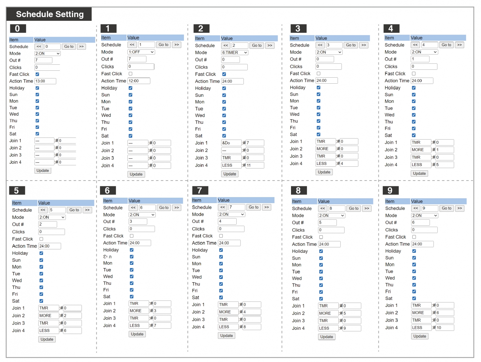
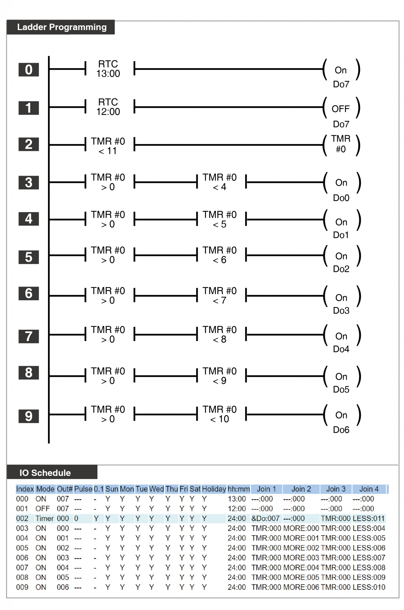
Sequentially triggers Y0~Y6 to create a running lights effect. The activation time is from 13:01 daily to 12:59 the next day, and it stops operating from 12:00 to 13:00 at noon.

Instruction Explanation:

  • Index 000: Daily trigger Y7 at 13:00.
  • Index 001: Daily OFF Y7 at 12:00.
  • Index 002: Set Timer000, starting condition is Y7 ON; TMR < 11 means this timer will cycle from 0 to 11.  ※ In this example, the timer unit is 0.1 seconds, checking Fast Click.
  • Index 003~ Index 009: Set the trigger conditions for Y0~Y6  When the time is within a certain segment of Timer 000, it will perform the ON action.

Referenced Commands:
Action Time / Timer / Fast Click / ON / OFF


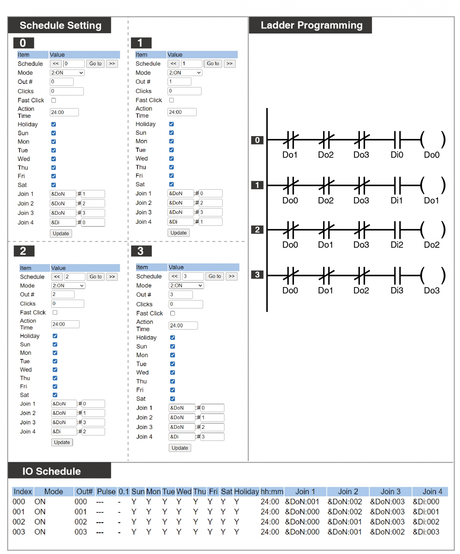
4 Doors Interlock: When one of the doors is unlocked, other 3 doors could not be unlocked until that door is closed 

Instruction Explanation:
1. When the door sensor DIX3 / DX5 / DIX7 and the door lock relay DOY2 / DOY4 / DOY6 of door B/door C/door D are closed, press Door A push button DIX0 , the door lock relay DOY0 can be trigger on 6 seconds.
2. When the fire alarm input DIX16 is closed, the door lock relay of door A/door B/door C/ door D can be released on;
3. When the door sensor DIX1 of door A is closed, the door lock relay of door A can be  automatically relocked;
4. When the door sensor DIX1 of door A is forced to open and the door relay DOY0 of door A is off, the alarm relay DOY1 of door A will be turned on;
5. When the door sensor DIX1 of door A is open, the timer TMR0 is triggered. When TMR0 is more than 8 seconds, the door open too long alarm relay DOY1 is triggered.
6. When the door sensor DIX1 of door A is closed, the alarm relay DOY1 can be stopped.


※Pipe output (Applicable to firmware version 5.06 and above, released on December 22, 2023)
Starting from this version, Pipe Output is supported. When the virtual output 255 is ON (as fixed conditions), it will trigger Pipe Output. This means that within the same time, 
Pipe outputs will not do the output simultaneously; instead, they will be queued and executed in the order of triggering.
※The schedule for selecting Pipe output will not be executed when the virtual output 255 is OFF.

Condition Requirements: 
There are three entrances to the parking lot, and each parking space is equipped with occupancy detection. When the parking system detects that the number of parking spaces is full, it will provide a signal to the 0808 PLC as a input to switch the barrier gate activation mode.

  • When parking spaces are not full: All three entrances can directly trigger the barrier gate through infrared sensing, allowing vehicles to enter the parking lot.
  • When parking spaces are full: The three entrances follow a queuing process. The one that first detects infrared signals will be given priority to enter the queue (Pipe). The barrier gates will be opened in a rotating manner through the queuing system to allow vehicles to enter.

Instruction Explanation:

  • Index 000: X4 is the signal input for full parking spaces, activating virtual output Y255 and switching the output mode to Pipe output.
  • Index 001~3: Queue output conditions. When the infrared edge trigger X0 is activated for the first entrance (output for ten seconds), and condition Y255 is ON, virtual point M8 is output. Similar conditions apply for the other entrances.
  • Index 004~6: General output conditions. When the infrared edge trigger X0 is activated for the first entrance (Latch output), and condition Y255 is OFF, virtual point M11 is output. Similar conditions apply for the other entrances.
  • Index 007~9: Combined conditions of Index 001~3 and Index 004~6. When M8 or M11 is triggered, output Y0. Similar conditions apply for the two other conditions.
  • Index 010~12: Conditions for closing virtual points Y11~Y13. After a vehicle passes through the barrier gate, the another infrared sensor should be triggered to execute the action of closing Y11~Y13.

Referenced Commands :
Pipe Output / Edge Trigger


Conditions:
There are two sets of motor devices on-site (Motor A/Motor B). Each day at noon (12:00), one set of motor is triggered for one hour. Motor A is the primary motor, and it operates when the counter of Motor A is less than or equal to the usage count of Motor B. Motor B is the secondary motor and operates when the counter of Motor B is less than the usage count of Motor A.

Instruction Explanation:

  • Index 000: When Y0 triggers Motor A, it synchronously triggers X0. A rising edge trigger on X0 increments the counter (CNT000) by 1.
  • Index 001: When Y1 triggers Motor B, it synchronously triggers X1. An rising edge trigger on X1 increments the counter (CNT001) by 1.
  • Index 002: When CNT000 is less than CNT001, trigger M8.
  • Index 003: When CNT001 is less than CNT000, trigger M9.
  • Index 004: When CNT000 equals CNT001, trigger M10.
  • Index 005: Set the trigger condition for Y0. Y0 is energized when either M8 or M10 is on, and M11 is also on. Ensure that Y0 is simultaneously wired to X0 for counting conditions.
  • Index 006: Set the trigger condition for Y1. Y1 is energized when M9 is on, and M11 is also on. Ensure that Y1 is simultaneously wired to X1 for counting conditions.
  • Index 007: Y11 will be turned ON at noon (12:00) as a necessary condition for motor triggering.
  • Index 008: Y11 will be turned OFF at 1:00 PM, stopping the motor output.
  • Index 009: Counter reset point. When the management center receives information that the motor usage has reached a certain count, the maintenance provider should be contacted for equipment maintenance, press the reset button (X2) to reset counter CNT000 after the maintenance.
  • Index 010: Same as Index 009, pressing the reset button (X2) resets counter CNT001.
  • Index 011: When CNT000 counts to 365, Y7 will be triggered, providing a warning signal to the management center. When this signal light is on, proactive contact with the maintenance provider is required.

Referenced Commands:
Edge Trigger (Rising) / Counter / CNT Comparison / Action Time 


Conditions:
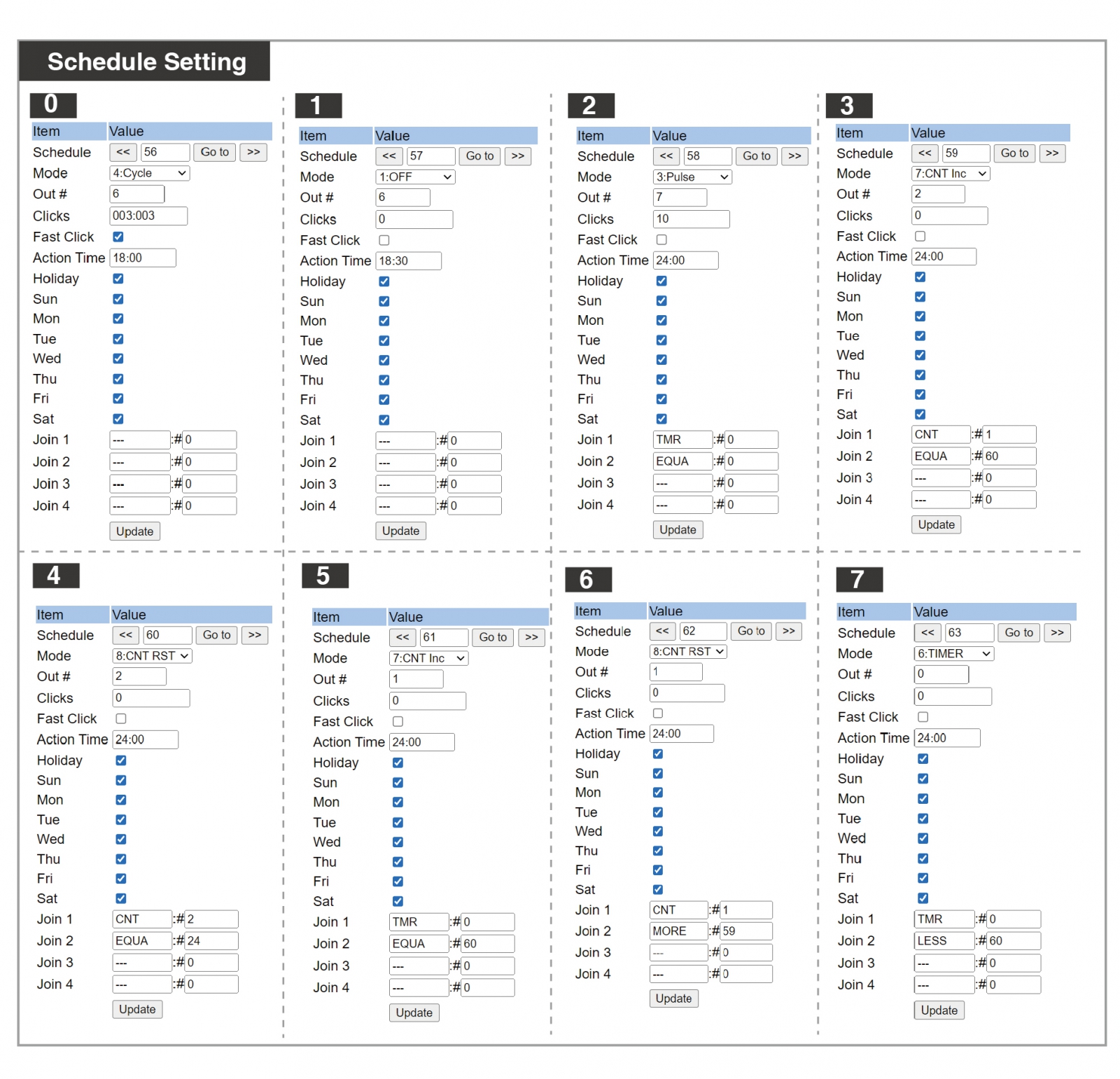
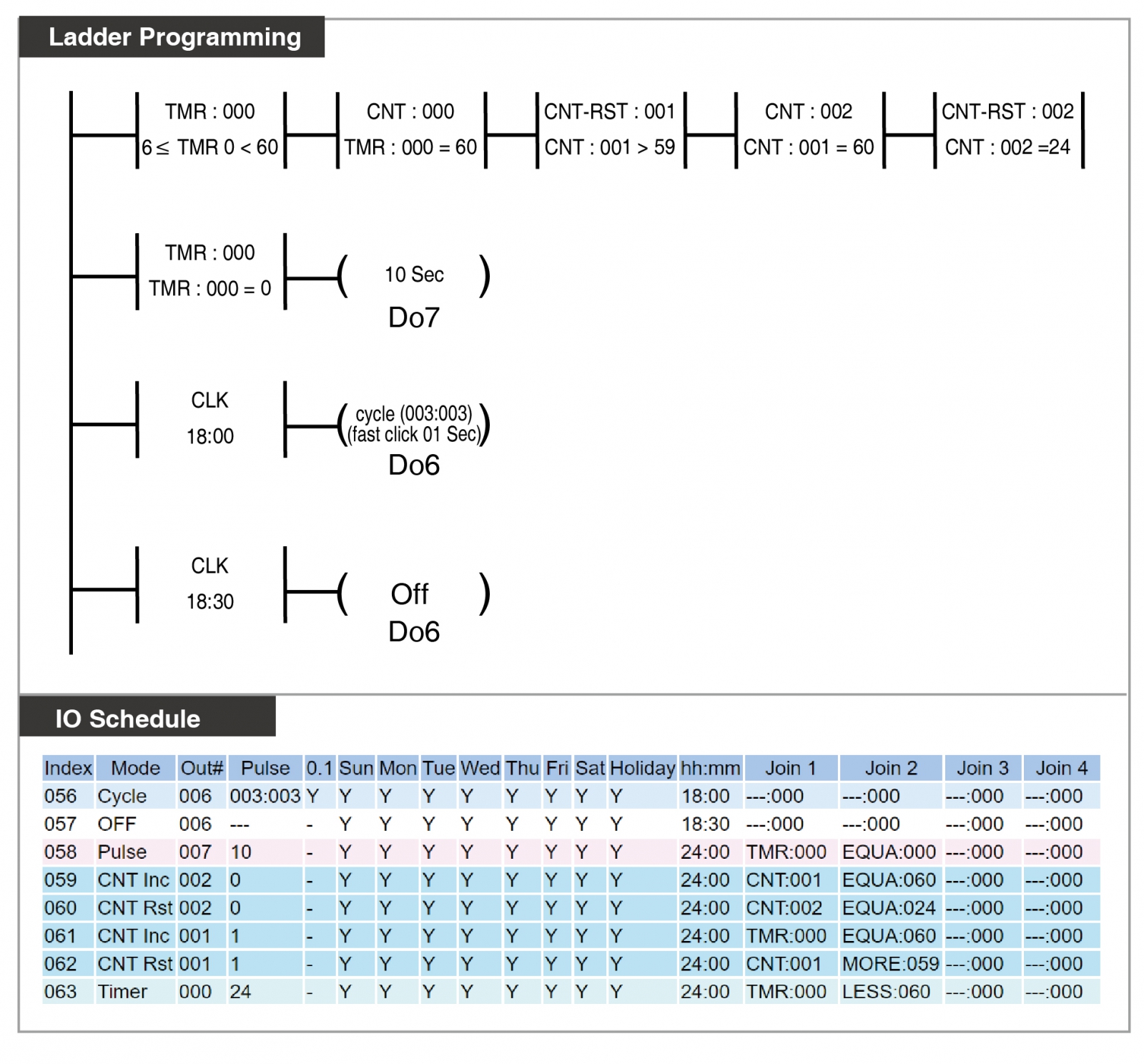
This method can generate a timer of any custom duration. In this example, a TIMER paired with a Counter creates a 24-hour cycle timer, which then triggers outputs at specific times. Following this logic, it can measure seconds, minutes, hours, days, months, years, etc., and specify conditions for triggering specific devices after a certain period.
A practical example: Patrolling point alarm output. Security personnel must swipe their security card at the site every hour. If there is no card swipe for over an hour, an alarm will be triggered at the security booth. If there is no card swipe for over three hours, an alarm will be triggered at the management center. This setup achieves different conditional alarms at multiple locations for different durations.

Instruction Explanation:

  • Indexes 000-004 form the 24-hour timer logic
  • Index 005-006 control the security booth alarm output
  • Index 007-008 control the management center alarm output
  • Index 000: TMR 000 cycles every 60 seconds
  • Index 001: (seconds) When TMR 000 = 60, Counter CNT 001 increments by 1
  • Index 002: (minutes) When CNT 001 = 60, Counter CNT 001 resets
  • Index 003: (hours) When CNT 001 = 60, Counter CNT 002 increments by 1
  • Index 004: (days) When CNT 002 = 24, Counter CNT 002 resets
  • Index 005: When CNT 002 > 0, it indicates that more than 1 hour has passed without a  security card swipe, triggering the alarm at the security booth (output Y0)
  • Index 006: On-site security mainframe relay controls input point X6. When triggered, it resets CNT 002 to 0, stopping the security booth/management center alarm outputs.
  • Index 007: When CNT 002 > 2, it indicates that more than 3 hours have passed without a security card swipe, triggering the alarm at the management center (output Y1)
  • Index 008: The management center has an external alarm cancel button controlling input point X7. When triggered, it resets CNT 002 to 0, stopping the security  booth/management center alarm outputs.


Related Resources:
 
 
Browsing Records
Go Top