Serial NO. : H04017003
Date of Editing : 2023-07-05
Content :
Table of Contents (Click to Jump to Content)
1. Introduction to Push Button Series
1-1 Touchless Infrared Button
1-2 Push Button Switch
1-3 Touchless Infrared Button + Push Button Switch
2. Touchless Infrared Button + Push Button Switch
3. LED Display Wiring Diagram for " Connect to Controller" and " Connect to Controller & Lock"
3-1. Wiring diagram for AR-PB2
3-2. Wiring diagram for AR-888-PBI-S
3-3. Wiring diagram for AR-101-PBI-L / AR-101-PBI-S
1. Wiring diagram for AR-101-PBI-L / AR-101-PBI-S
SOYAL Push buttons can be categorized into the following three types: Touchless Infrared Button, Push Button Switch, and n Touchless Infrared Button + Push Button Switch.
1-1 Touchless Infrared Button
1-2Push Button Switch
 |
(AR-PB5) ( AR-PB5-P) |
| Push Button Switch AR-PB-2 | Stainless Steel Push Button (No Power Supply Needed) AR-PB5 |
.png)
1-3 Touchless Infrared Button + Push Button Switch
 |  |
| Touchless Infrared Sensor Push Button(Anti-Interference) AR-101-PBI-L | Touchless Infrared Sensor Push Button(Anti-Interference) AR-101-PBI-S |
► Selection Guide of Touchless Infrared Button AR-101PBI-L & AR-101PBI-S
2. Push Button Comparison Table
| Touchless Infrared Button | Push Button Switch | Touchless Infrared Button + Push Button Switch | |||
| Touchless Infrared Button + Push Button Switch | AR-888-PBI | AR-PB-2 | AR-PB-5 | AR-101-PBI-L | AR-101-PBI-S |
| Product |  | | .png) | | |
| Instructions for use | Non-contact Infrared | Physical Button | Non-contact Infrared / Physical Button | ||
| Active distance | 2~10cm | X | 0.5-8cm | 0.5-15cm | |
| LED | Yes(Standby red light, door open green light.) | Yes(Standby red light, door open green light.) | No | Yes(Standby Green light, door open red light.) | |
| LED Wiring Diagram | Detailed wiring diagram (Click to Jump to Content) | Detailed wiring diagram (Click to Jump to Content) | No | Detailed wiring diagram (Click to Jump to Content) | Detailed wiring diagram (Click to Jump to Content) |
| LED Wiring Diagram | No | No | DPLA-101PB-L-6/7/8A / DMET-101PJ01/05/03 | DMET-101PJ01/05/03 | |
3. LED Display Wiring Diagram for " Connect to Controller" and " Connect to Controller & Lock”
3-1. Wiring diagram for AR-PB2
| Product | | |
| LED display status | Connect to Controller | Connect to Controller & Lock |
| Wiring Diagram | 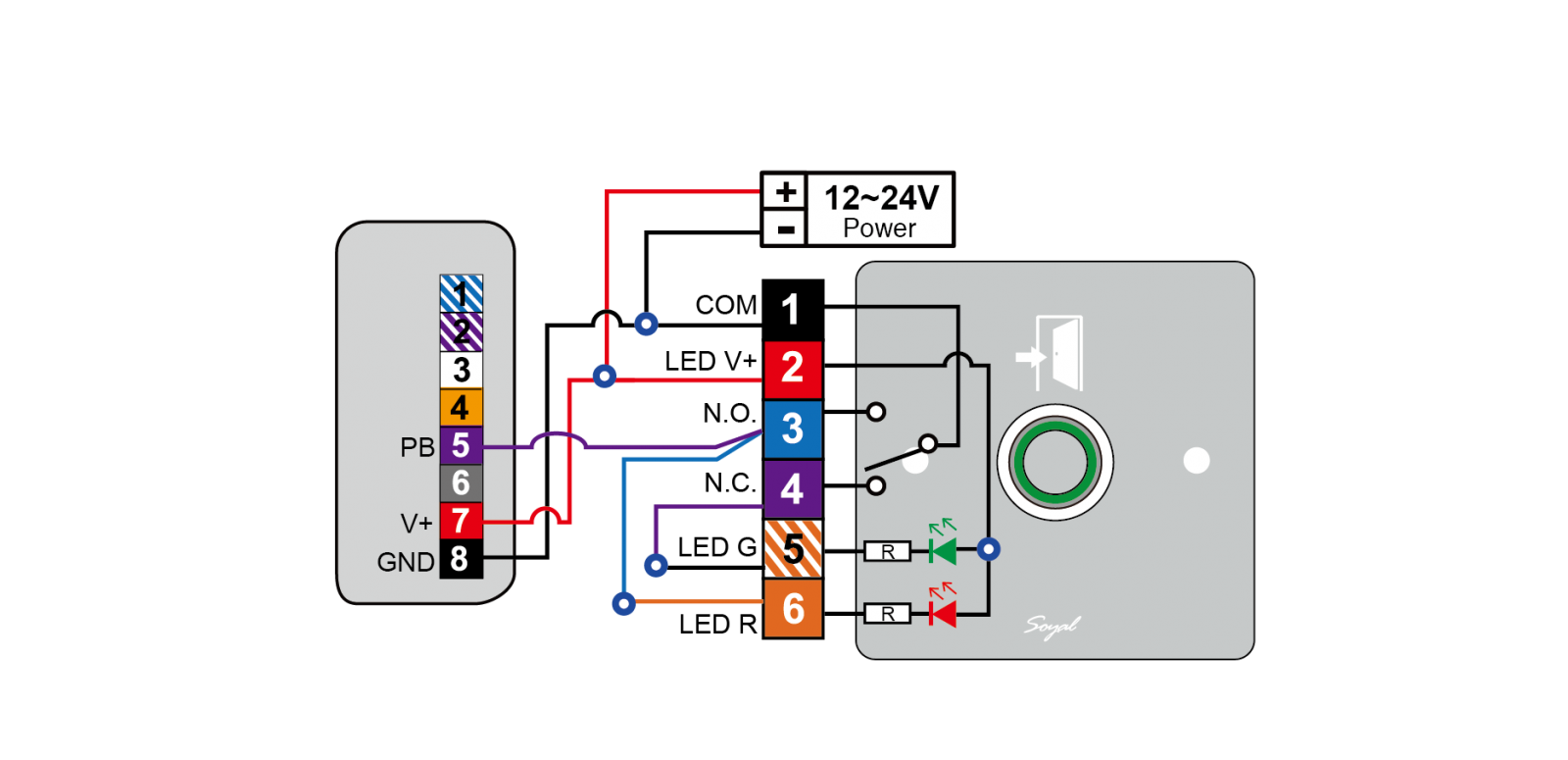 | 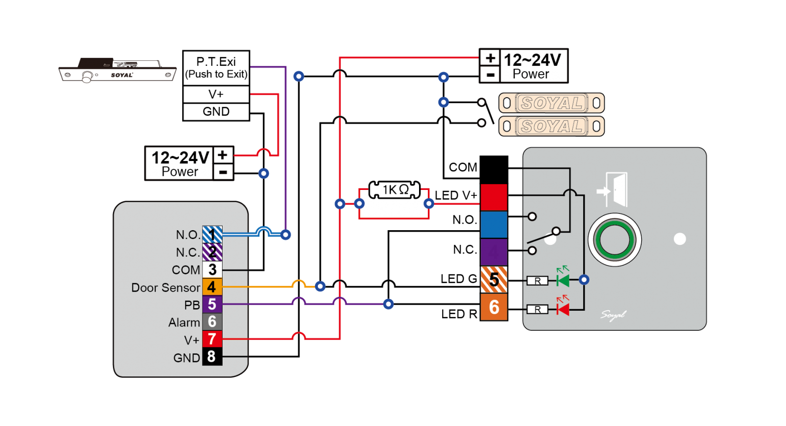 |
| (Default) LED Color |
|
|
 Green LED: Standby status indicator
  Red LED: Displaying red light when the
3-2. Wiring diagram for AR-888-PBI-S
| Product | | |
| LED display status | Connect to Controller | Connect to Controller & Lock |
| Wiring Diagram | 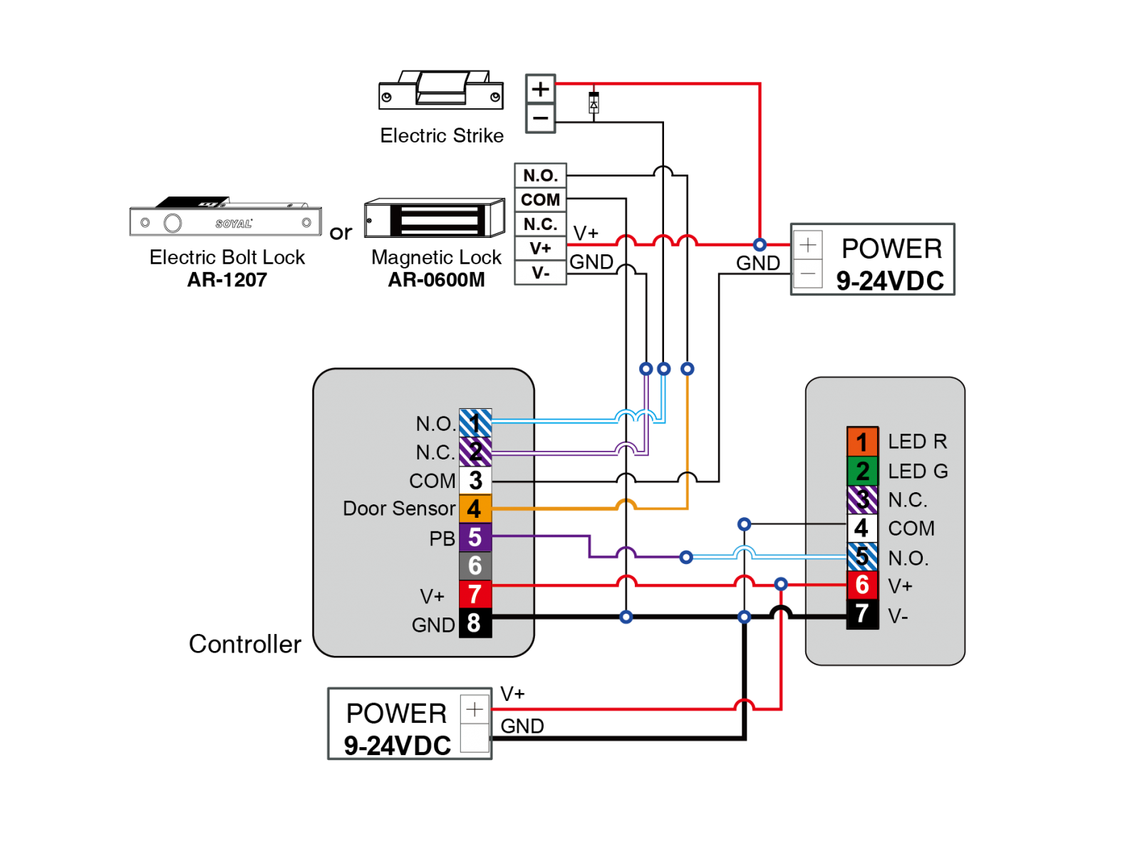 | 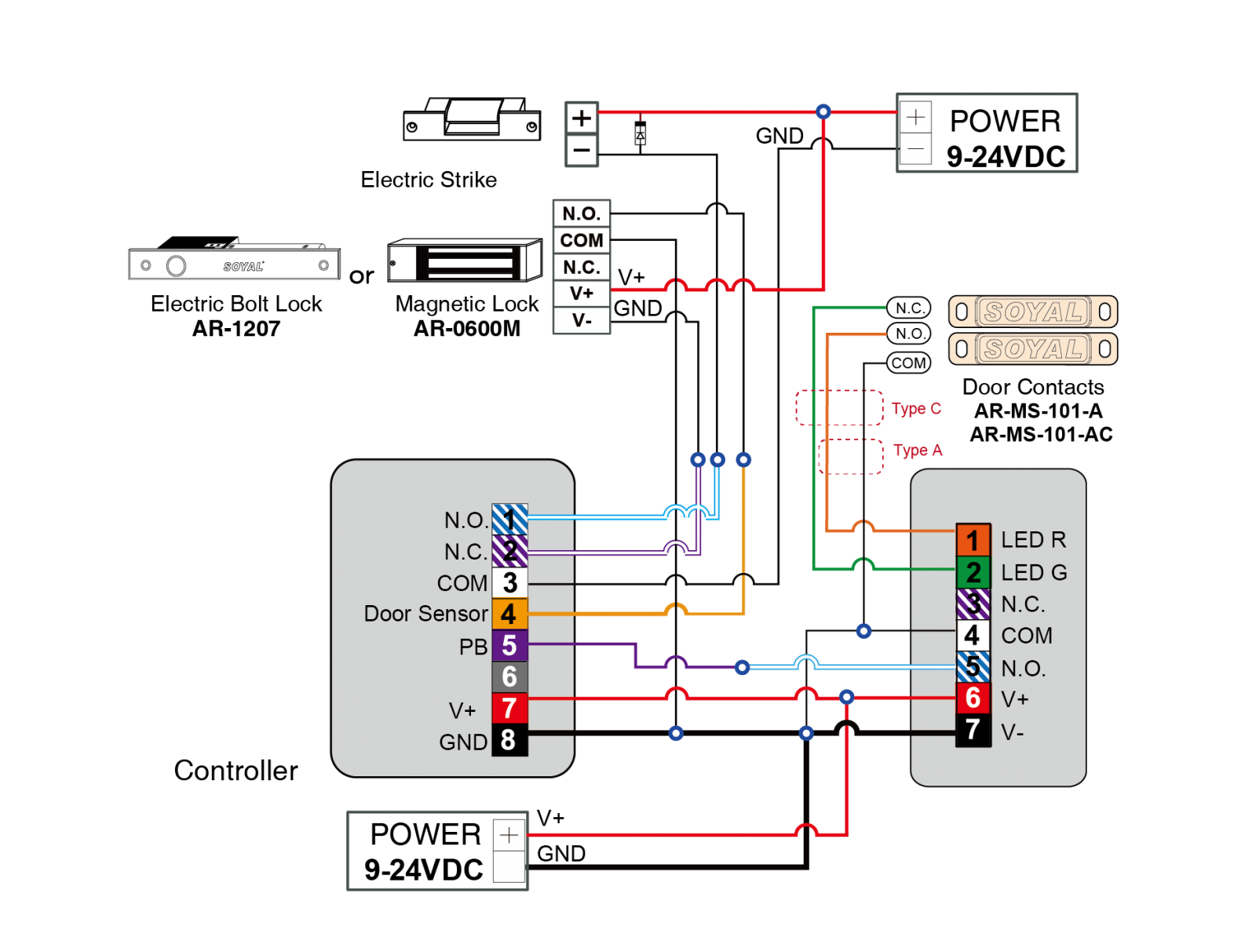 |
| (Default) LED Color |
|
|
3-3. Wiring diagram for AR-101-PBI-L / AR-101-PBI-S
| Product | | |
| LED display status | Connect to Controller | Connect to Controller & Lock |
| Wiring Diagram | | |
| (Default) LED Color |
|
|