Serial NO. : H01614005-EN
Date of Editing : 2024-01-26
2-1 Set the Node ID of AR-716-E18
2-2 Connect and programming AR-716-E18
2-3 Connect readers under AR-716-E18
2-4 Connect H/E series Controllers under AR-716-E18
2-5 Set the Door Number of H/E series reader under AR-716-E18
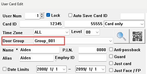
2-6 Door Group Creation and Operation
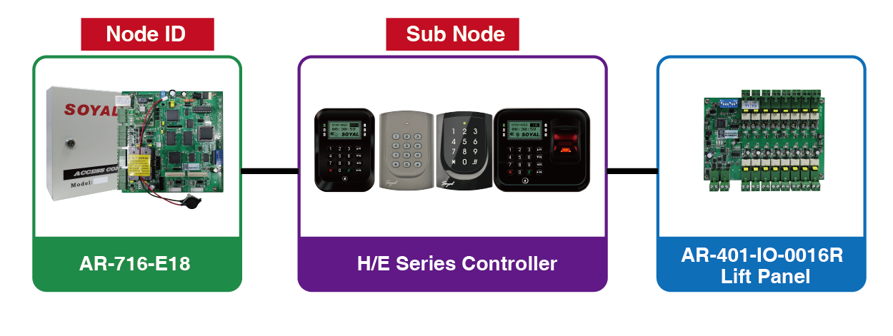
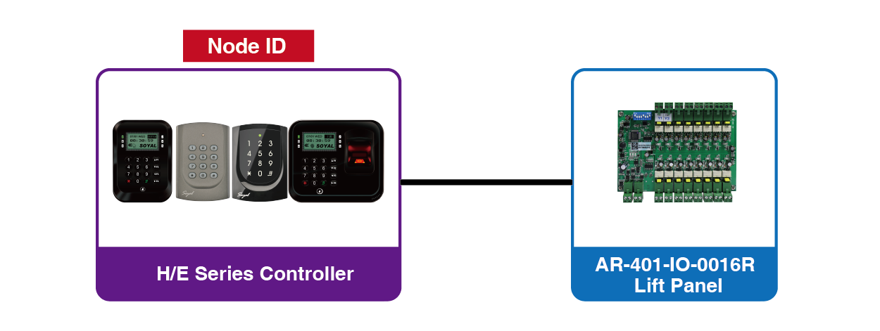
3-1 H/E Series Controller + AR-401-IO-0016
3-2 AR-716-E18 + H/E Series Controller + AR-401-IO-0016
4. More than 2 pcs of H/E Series Controllers connect to AR-716-E18
5. 2 pcs of Wiegand Readers connect to AR-716-E18
1. Introduction
Manual Link ▶ AR-716-E18 Manual
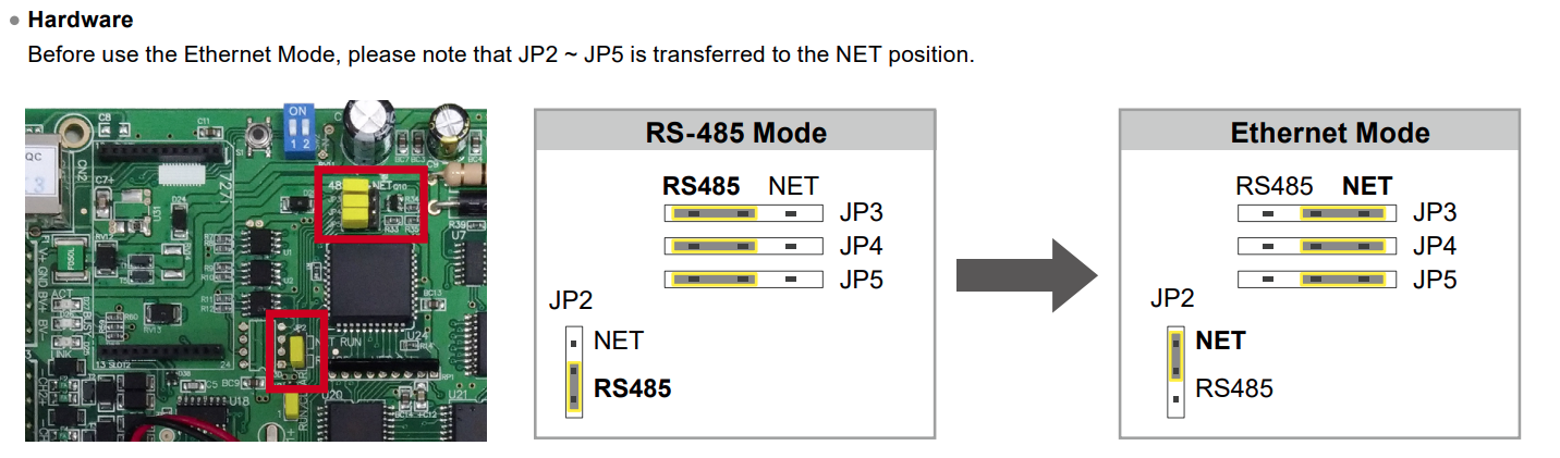
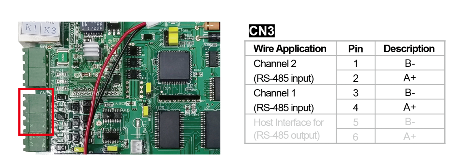
1. AR-716-E18 is available to be connected with TCP/IP(CN2) or RS-485(CN3-Pin5/6), notice that the JP2/3/4/5 have to change when you modify the communication of TCP/IP and RS-485.
AR-716-E18 is available to be standalone mode when we finish all settings.
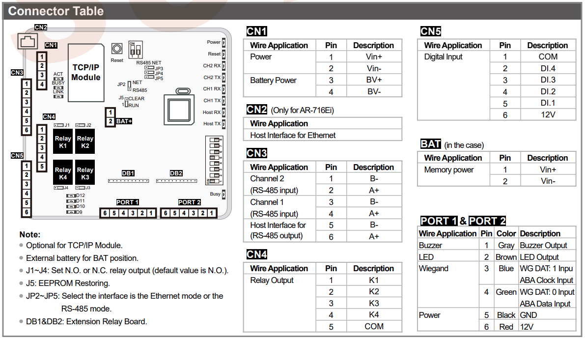
2. H/E Series Controller is available to be connected with AR-716-E18 via Channel 1 & 2, Channel 1 for Node ID of 1~8 of H/E Series Controllers, Channel 2 for Node ID of 9~16 of H/E Series Controllers.
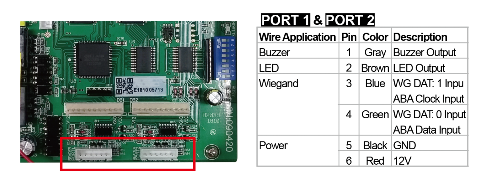
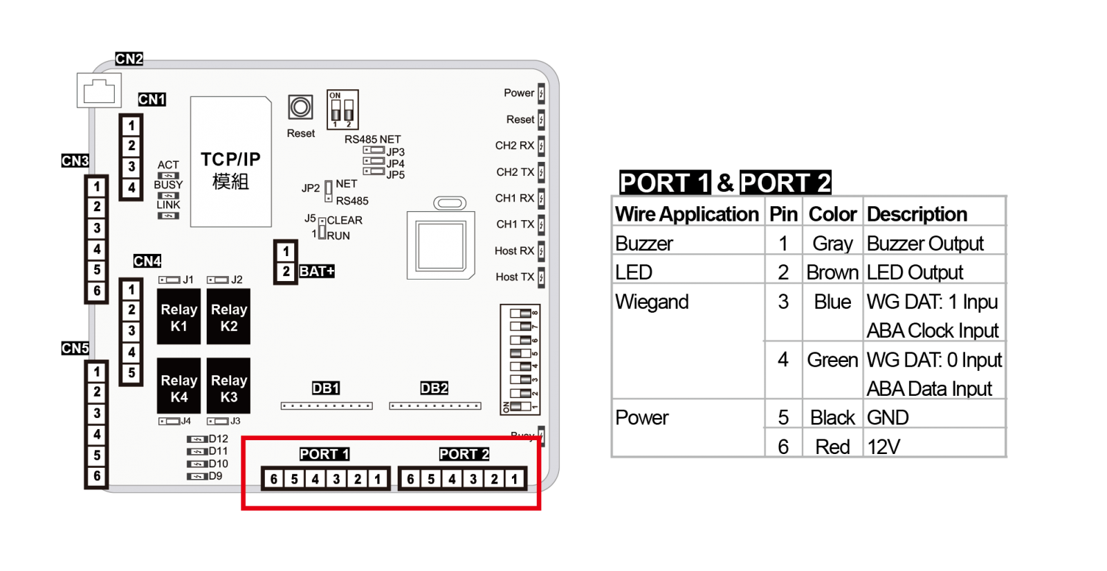
3. Port 1/2 are WG ports, could connect to K/U series reader and AR-661UG UHF reader.
2. Settings of AR-716-E18
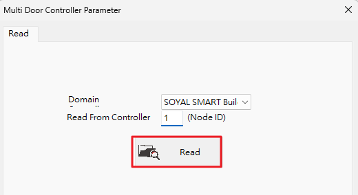
Step1. Select 716E icon and input the Node ID of AR-716-E18, select “Read”.
.png)
Step2. Here now we could set all of the parameters of AR-716-E18
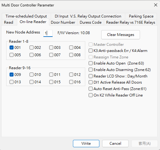
※ Please note that Wiegand Reader requires to be connected to common ground. The WG terminals of AR-716-E18 provide Power output and can be directly utilized. For details, refer to ➔5. 2 pcs of Wiegand Readers connect to AR-716-E18
※ H/E series controllers can be externally powered and only need to send RS485 signals to AR-716-E18. Please note that CH1 is for connecting controllers with Node ID from 001 to 008, while CH2 is for controllers with Node ID from 009 to 016.
For detailed instructions, refer to ➔4. More than 2 pcs of H/E Series Controllers connect to AR-716-E18.
AR-716-E18 allows you to specify the Door Number for each H/E series controller, which is used to display specific Door Names and configure Door Group. The common door number structure can be referred to in the following link.
In the example of the FAQ, we use the new version of the AR-716-E16 multi-door controller, and the door number configuration is identical when using AR-716-E18, only the setting interface differs.
FAQ➔Door Number Setting of SOYAL Controllers and Readers
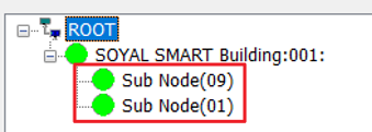
Step1. Confirm the AR-716-E18 Area and H/E Series Controllers are all online.
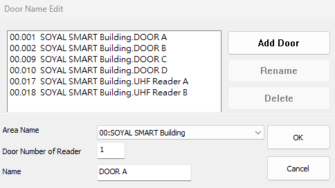
Step2. Assign the Door Name to specified Door Number
701ClientSQL > A. Door Name Edit > Add Door > Select Area, Door Number > Setting Door Name 
Step3. Set Door Group in  9.Door Group Edit
Refer to the reality case of below, you could quickly understand how to use Door Group successfully.
➔ How to utilize door group function to restrict access of specified doors during national holidays?
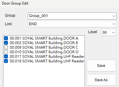
Step4. Assign the Group_001 to the user, and the user who has the card may get access on specified doors of Door A/B and UHF Readers.
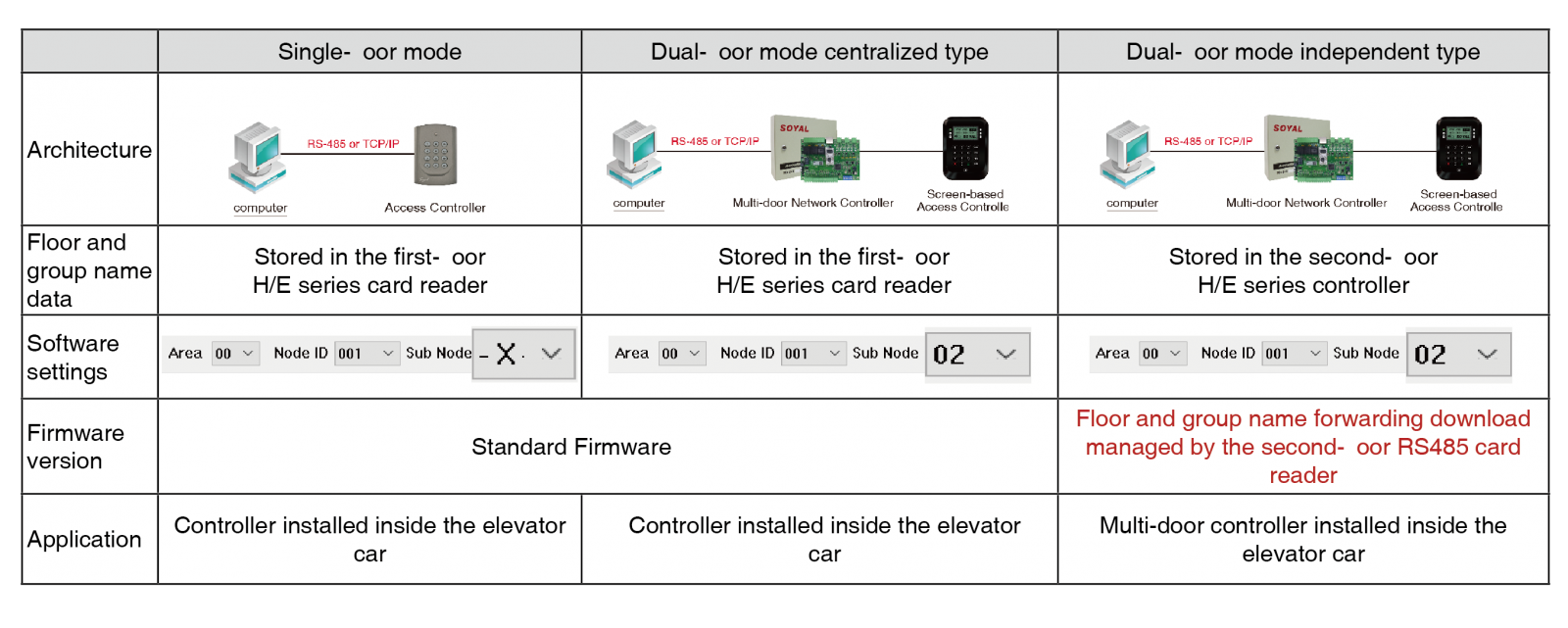
In the standard firmware of H/E Series Controller, the access floor data is saved in the H/E Series Controller directly, even if you connect the H/E Series Controller to the AR-716-E18, 701ClientSQL will bypass the access floor data to H/E Series Controller.
In 701ClientSQL software version 10.5 and above, there is an upgraded floor control configuration interface, making it easier to operate and understand.
※ When the architecture includes AR-716-E16/AR-716-E18 multi-door controllers, please note that 701ClientSQL needs to be updated to version 240206 or later.
In the new version of the floor configuration interface, you can directly specify the elevator number and allocate the card reader paired with that number to a specific area and station number.
There are two locations within the software where you can access the floor configuration interface.
- The elevator icon in the upper-right corner allows direct access to the new version of the lift control editing interface.
.png)
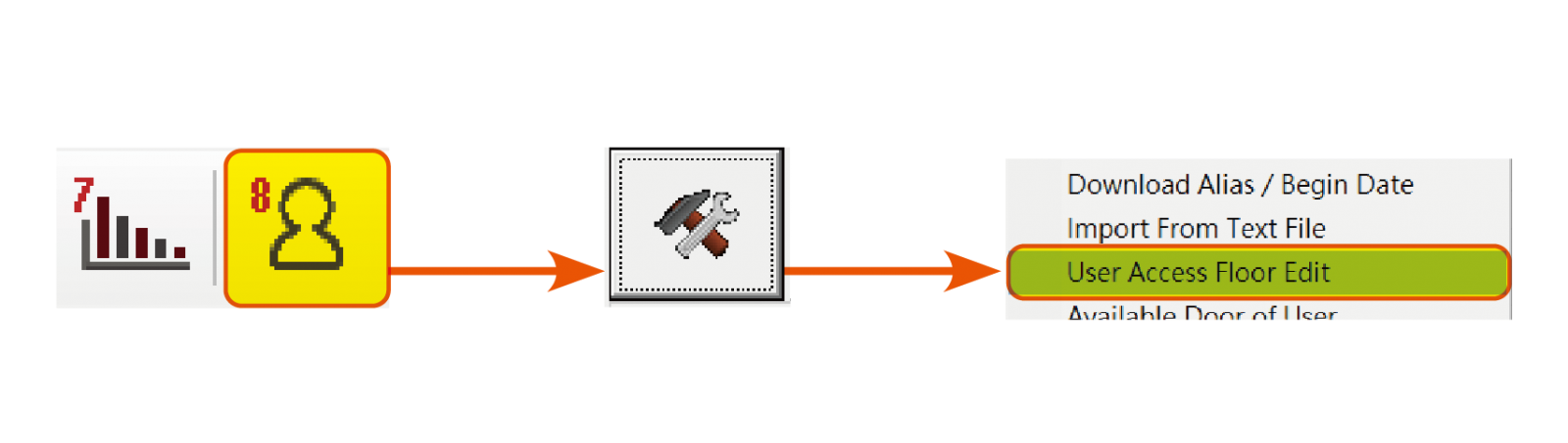
 8.User Cards Edit > Tools Box > User Access Floor Edit
This method can open either the old version or the new version of the lift control interface.
The default is the new version, and you can follow the instructions in Section 11.1 of the 701ClientSQL manual to switch to the old version through Regedit.
Step.2 Dialog and button functions
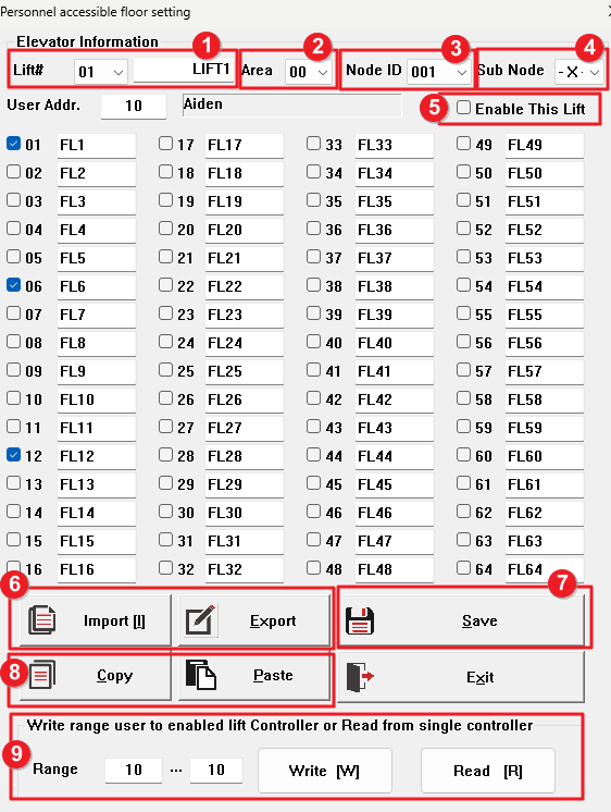
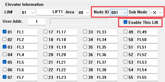
1. Lift Code (Lift #): You can choose the number from 01 to 36 and customize the elevator name for easy reference.
2. Area: The area code of the card reader used by the elevator.
3. Node ID/ 4. Sub Node: Fill in the device Node ID according to the structure.
3-1 For multi-door controller (AR-716-E16/AR-716-E18) + H/E series controllers structure, the Node ID has to filled in the Node ID of multi-door controller, and the Sub Node is the Node ID of the H/E series controller.
3-2 When the H/E series controller operates independently, Node ID has to filled in the Node ID of the H/E series controller, and the Sub Node is selected as X.
5. Enable This Lift: When checked, the downloaded elevator operates normally with floor setting content. When unchecked, card swiping does not trigger the AR-401-IO-0016 lift control board.
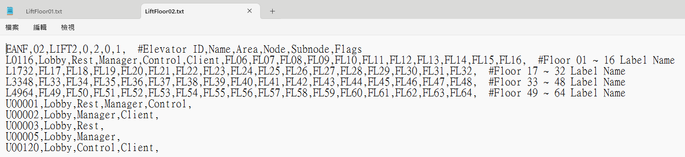
6. Import/Export: Import or export floor data. The text file can be edited to include the above items 1-5, as well as the names of each floor and the floors accessible by each user.
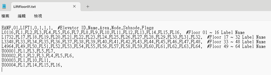
Definition:
| ENAF | 01 | LIFT1 | 0 | 1 | 1 | 1 |
| Identifier | Lift Code | Lift Name | Area | Node ID | Sub Node | Enable Lift |
| Do not modify | 01~36 | Self-define | Area selected in 701ServerSQL | *Note 1 | *Note 1 | 1 for Enable; 0 for disable |
| L0116 L1732 L3348 L4964 | FL1 | FL2 | … | FL16 | #Floor01~16 #Floor17~32 #Floor33~48 #Floor49~64 |
| Lobby | Rest | … | FL16 | ||
| Lloor Range | Floor Name | Range Hint | |||
| Do not modify | Self-define | Self-define | Self-define | Self-define | Do not modify |
※ In practical operation, it is recommended to complete the above settings in the 701ClientSQL lift control interface first, and the values will be automatically populated into the text file.
| U00001 | Lobby | Rest | Manager | Client |
| U00002 | Lobby | Manager | Client | |
| U00120 | Lobby | Control | Client | |
| User Address | Floor Name, directly filled in the Floor Name is available. | |||
Note 1:
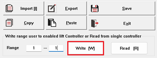
7. Save: After selecting the user address and checking the completed accessible floors, you need to click "Save" before downloading or jumping to another user's position to continue editing their accessible floors.
8. Copy/Paste: Copy the accessible floors of the current user address and paste same into other user positions.
※This feature is convenient for setting the accessible floors of residents or offices on the same floor at once.
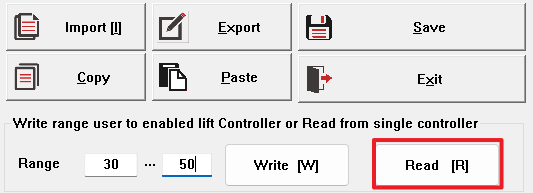
9. Write/Read: After setting the user address range, you can choose "Write" or "Read" to update the personnel's accessible floors. When setting data for a single user, you can enter 1~1 or 5~5, which means updating the data for a single person.
Step.1 Confirm the connection status between the Multi-door controller and H/E series controller.

Step.2 Open the 701ClientSQL lift setting interface and check the floors accessible by the user.
※For selecting Lift Code/Area, please refer to the above instructions for the new version floor control interface.
Step.3 Check "Enable This Lift"
Step.4 Select "Save" and enter the range 1~1, then choose "Write."
※When editing existing user data, please read back to confirm the current accessible floors before reselecting.
Example: In a community using user address 1~500, if you need to edit the accessible floors for address 30~50, you can enter the range 30~50 and then choose "Read". After that, continue editing the accessible floors.
The sequence of actions in the video is as follows:
- AR-716-E18 is connected using the AR-321-CM converter.
- AR-716-E18 is powered on.
- AR-725E (configured as Node ID 001) is connected via RS485 to CH1 and powered on.
- AR-725E CN9 is connected to the AR-321L485-5V converter, then connected to the AR-401-IO-0016R floor control board.
- Verify that the AR-401-IO-0016R DIP Switch is set to 1/8 ON (refer to the AR-401-IO-0016R manual for detailed definitions).
- Confirm that the Node ID of AR-716-E18 is set to 001.
- Test card swiping; if all relays on AR-401-IO-0016R are ON, it indicates that the device wiring is correct.(*When a valid card has not been set for accessible floors, it defaults to triggering all relays to facilitate checking the normal operation of the device.)
- Go back to the lift setting in 701ClientSQL, enter the user address of the card, and input the Lift Code/ Node ID of controller and etc. (please refer to the new interface explanation of 3. Node ID/ 4. Sub Node).
- Check the specified relay options and test points 1/2.
- Choose “Save” to save the settings, and select the download range for user address 5~5. Then choose “Write” to Controller.
- Test card swiping; if relays 1/2 are ON only, it indicates that the settings are complete.
Step1. Confirm the connection status between the Multi-door controller and H/E series controller.
Step.2 Open the 701ClientSQL lift setting interface and check the floors accessible by the user.
※ For selecting Lift Code/Area, please refer to the above instructions for the new version floor control interface.
Step.3 Check "Enable This Lift"
.png)
Step.4 Select "Save" and enter the range 1~1, then choose "Write."
※ When editing existing user data, please read back to confirm the current accessible floors before reselecting.
Example: In a community using user address 1~500, if you need to edit the accessible floors for address 30~50, you can enter the range 30~50 and then choose "Read". After that, continue editing the accessible floors.
The sequence of actions in the video is as follows:
- AR-716-E18 is connected using the AR-321-CM converter.
- AR-716-E18 is powered on.
- AR-725E (configured as Node ID 001) is connected via RS485 to CH1 and powered on.
- AR-725E CN9 is connected to the AR-321L485-5V converter, then connected to the AR-401-IO-0016R floor control board.
- Verify that the AR-401-IO-0016R DIP Switch is set to 1/8 ON (refer to the AR-401-IO-0016R manual for detailed definitions).
- Confirm that the Node ID of AR-716-E18 is set to 001.
- Test card swiping; if all relays on AR-401-IO-0016R are ON, it indicates that the device wiring is correct. (※When a valid card has not been set for accessible floors, it defaults to triggering all relays to facilitate checking the normal operation of the device.)
- Go back to the lift setting in 701ClientSQL, enter the user address of the card, and input the Lift Code/ Node ID of controller and etc. (please refer to the new interface explanation of 3. Node ID/ 4. Sub Node).
- Check the specified relay options and test points 1/2.
- Choose “Save” to save the settings, and select the download range for user address 5~5. Then choose “Write” to Controller.
- Test card swiping; if relays 1/2 are ON only, it indicates that the settings are complete.
4. More than 2 pcs of H/E Series Controllers connect to AR-716-E18
In this example, the AR-716-E18 is connected to two controllers (AR-725-E/AR-721-H). The AR-716-E18 restricts CH1 to connect to controllers with Node ID 001 to 008, and CH2 to connect to controllers with Node ID 009 to 016.
AR-725-E is set with Node ID 001 and connected to CH1, while AR-721-H is set with Node ID 009 and connected to CH2. In practical use with more controllers, you can independently assign the amount of controllers to CH1 or CH2.
The video demonstrates the following steps:
- AR-716-E18 is connected using the AR-321-CM converter.
- AR-716-E18 is powered on.
- AR-725E is connected via RS-485 to CH1 (configured with Node ID 001).
- AR-725E is powered on (white relay COM is connected to ground, orange door position detection is not connected to a magnetic switch, so it's grounded either).
- AR-721H is connected via RS-485 to CH2 (configured with Node ID 009).
- AR-721H is powered on (white relay COM is connected to ground, orange door position detection is not connected to a door sensor, so it's grounded either).
- Using a card, sequential swiping is performed on both controllers, displaying card swipe messages (-01: Door A represents messages from AR-725E / -09: Door C represents messages from AR-721H).
(※Within the parameter settings of AR-716-E18, the AR-725E with Node ID 001 is assigned as Door Number 1, and the AR-721H with Node ID 009 is assigned as Door Number 9, refer to➔ 2-5 Set the Door Number of H/E series controller under AR-716-E18.)
STEP1. Set the Node ID for H/E series controllers. For other controller models, refer to its manuals.
AR-725-E: .png) 123456
123456.png) Enter programming mode➔ 00001# ➔ Exit
Enter programming mode➔ 00001# ➔ Exit
AR-721-H: 123456Enter programming mode ➔ 00009# ➔ Exit
STEP2. Connect the devices and ensure that both AR-716-E18 and the underlying H/E series controllers are in connected state.
Key points:
- The communication jumper on AR-716-E18 is set to RS-485 or TCPIP.
- The communication cable of AR-716-E18 is connected to RS-485 or TCPIP.
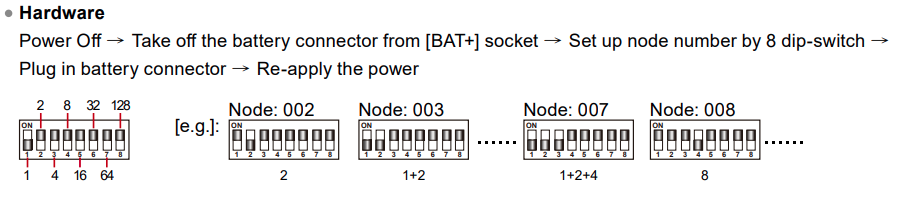
- Adjust the Node ID of AR-716-E18 using the DIP switch.
- The RS-485 communication cable of H/E series controllers is connected to AR-716-E18.
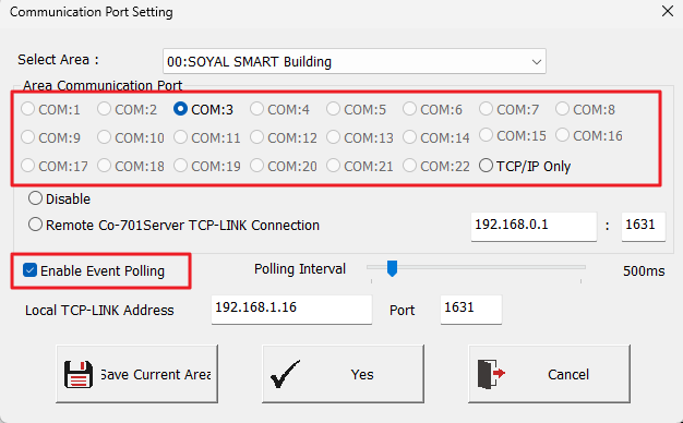
STEP3. Configure the communication options for 701ServerSQL and check “Enable Event Polling”
If the architecture only involves RS-485 devices, choose COM.
If the architecture only involves TCP/IP devices, select TCP/IP Only.
For configuration with both RS-485 and TCP/IP devices, choose COM, and the TCP/IP system will be automatically detected.
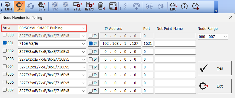
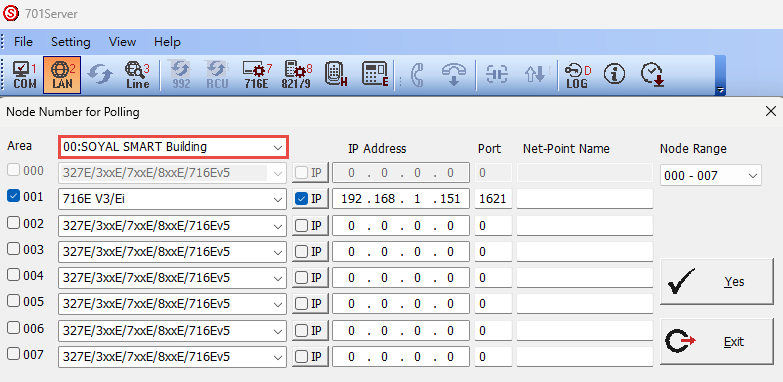
STEP4. Choose LAN .png) and configure the 716E18 model option as “716E V3/Ei”
and configure the 716E18 model option as “716E V3/Ei”
If using TCP connection, enter the corresponding IP Address / Port on the right and check the 'IP' option. If connecting via RS-485, do not check the 'IP' option, and leave the IP Address / Port blank.
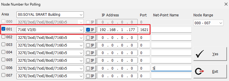
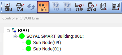
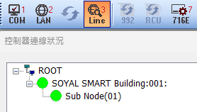
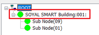
And then confirm the online status of AR-716-E18.
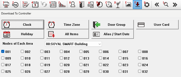
STEP5. Select the 716E option  for 701ServerSQL, choose the controller area, and click 'Read.
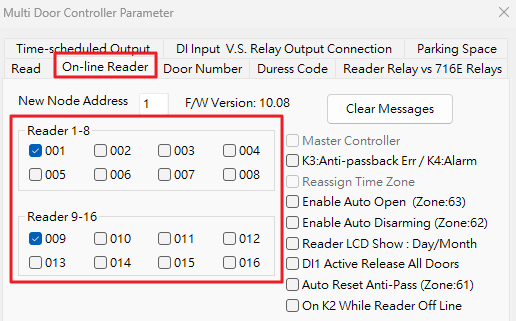
STEP6. Check the Node ID for the current connection in the H/E series card reader. Currently using CH1 Node ID 001 (AR-725-E) / CH2 Node ID 009 (AR-721-H).
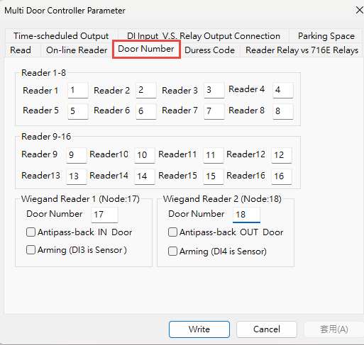
STEP7. Set the door number according to the detailed pairing method in the following link, Chapter 2-4:
FAQ: Door Number Setting for Connecting Multiple Controllers to H/E Series Card Readers
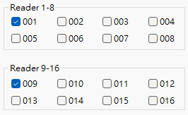
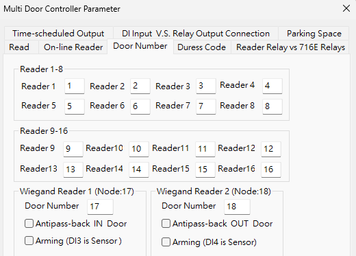
The fields to the right of Reader 1~16 indicate assigning door numbers for readers with Node ID 1~16.
Example: Input 1 for Reader1, signifying assigning door number 1 to AR-725E with Node ID 001.
Example: Input 9 for Reader9, signifying assigning door number 9 to AR-721H with Node ID 009.
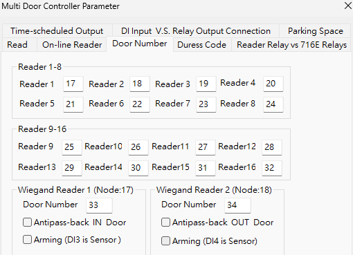
In the on-site structure, there may be multiple AR-716-E18 units. In this case, door numbers should not be repeated, while Node IDs are set to 1~16 because they are connected under AR-716-E18.
Example: Input 17 for Reader1, signifying assigning door number 17 to AR-725E with Node ID 001.
Example: Input 25 for Reader9, signifying assigning door number 25 to AR-721H with Node ID 009."
STEP8. Confirm the controller status of H/E series controllers
STEP 9. And now we can upload the card data to AR-716-E18 via 701ClientSQL.
5. Two pcs of Wiegand Readers connect to AR-716-E18
When the reader is connected to AR-716-E18, card number identification and relay triggering are both processed by AR-716-E18. K/U series readers and AR-661UG reader only have reading capabilities.
In this example, AR-716-E18 is connected to two AR-725U units for demonstration.
AR-716-E18 WG PORT Wiring Definitions:
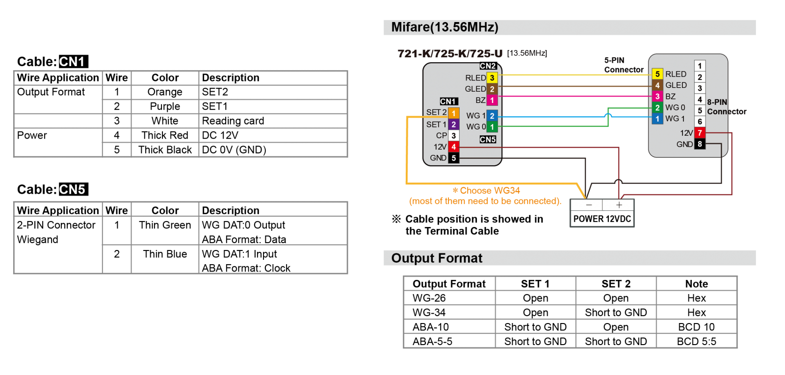
Wiring Definitions for AR-725U (Mifare type):
In the example, only CN1 is used to connect power, and the orange wire is grounded (WG34 format). Additionally, CN5 is used for WG output. If you need to use the red/green LED inputs and other functions, or looking for EM type wiring, please refer to the ➤ reader's manual for guidance.
In the video, the following sequence can be observed:
- AR-716-E18 connected using AR-321-CM converter.
- AR-716-E18 connected to power.
- WG output (blue/green) from the AR-725U card reader connected to the WG input (blue/green wires) of AR-716-E18.
- Power lines (red/black) from AR-725U card reader connected to WG power output of AR-716-E18.
- Orange wire from AR-725U connected to ground (WG34 card number output format).
- Using a card to sequentially swipe between the two card readers, triggering card swipe messages (-17 indicates a message from WG PORT0, -18 indicates a message from WG PORT1).
STEP1. Connect the devices and ensure that AR-716-E18 and the underlying H/E series card readers are in a connected state.
Key points:
- Set the communication jumper on AR-716-E18 to RS-485 / TCPIP.
- Connect the communication line of AR-716-E18 to RS-485 or TCPIP.
- Adjust the Node ID of AR-716-E18 through the DIP switch.
- Connect WG DATA 0/1 communication lines from Wiegand card readers to AR-716-E18.
STEP2. Configure the communication options for 701ServerSQL and check “Enable Event Polling”
If the architecture only involves RS-485 devices, choose COM.
If the architecture only involves TCP/IP devices, select TCP/IP Only.
For configuration with both RS-485 and TCP/IP devices, choose COM, and the TCP/IP system will be automatically detected.
STEP3. Choose LAN and configure the 716E18 model option as “716E V3/Ei”
If using TCP connection, enter the corresponding IP Address / Port on the right and check the 'IP' option. If connecting via RS-485, do not check the 'IP' option, and leave the IP Address / Port blank.
And then confirm the online status of AR-716-E18.
STEP4. Select the 716E option for 701ServerSQL, choose the controller area, and click 'Read.
STEP 5. Check the Door Number for the current connection in the WG reader.
The details of Door Number can refer to 2-6 Door Group Creation and Operation
.png)
STEP7. As the reader only sends WG signals to AR-716-E18, 701ServerSQL cannot view the connection status of the reader itself. Therefore, open 701ClientSQL and confirm signal reception by swiping a card. When swiping a card on the reader, you will see card message with the code -17 for the WG reader connected to PORT1 and -18 for the WG reader connected to PORT2.
※Index 7/8 represent records of invalid cards before downloading to AR-716-E18, and Index 13/14 represent records of normal entries and exits after downloading the cards to AR-716-E18.
.png)